Chapter 6 - Parameter Description [I/O]
6-53
[PID operation selection], APP-80 [Ext. PID
operation selection] and APP-62 [PID Bypass
selection]. Then, set one of the desired unit among
Percent, Bar, mBar, kPa, and Pa in I/O-86, 86, 88. In
this case, all unit display related to inverter target
frequency are changed.
When APP-02 [PID operation selection], APP-80
[Ext. PID operation selection] and APP-62 [PID
Bypass selection] setting value is “0”, I/O-86, -87, -
88 are initialized to Speed [Hz]. If DRV-16 is
changed to [Rpm], unit display is changed from [Hz]
to [Rpm].
I/O-90, 91: Inverter Number, Baud Rate
I/O-92, 93: Operation method when
communication signal is lost, Communication
Time Out
I/O-94: Communication Delay Time
I/O-90 [Inverter Number] sets the inverter ID to
perform RS485 communication with PC. I/O-91
[Baud rate] sets the communication speed. To make
the multi-drop system, connect the terminal C+ to
other inverter’s C+ and C- to C-.
I/O-92, 93 are only displayed when DRV-03 [Drive
mode] or DRV-04 [Frequency mode] is set to 4 “Int.
485”.
In this case, the LCD display shows “LOR”.
I/O-93 [Communication time out] determines
whether the signal is lost.
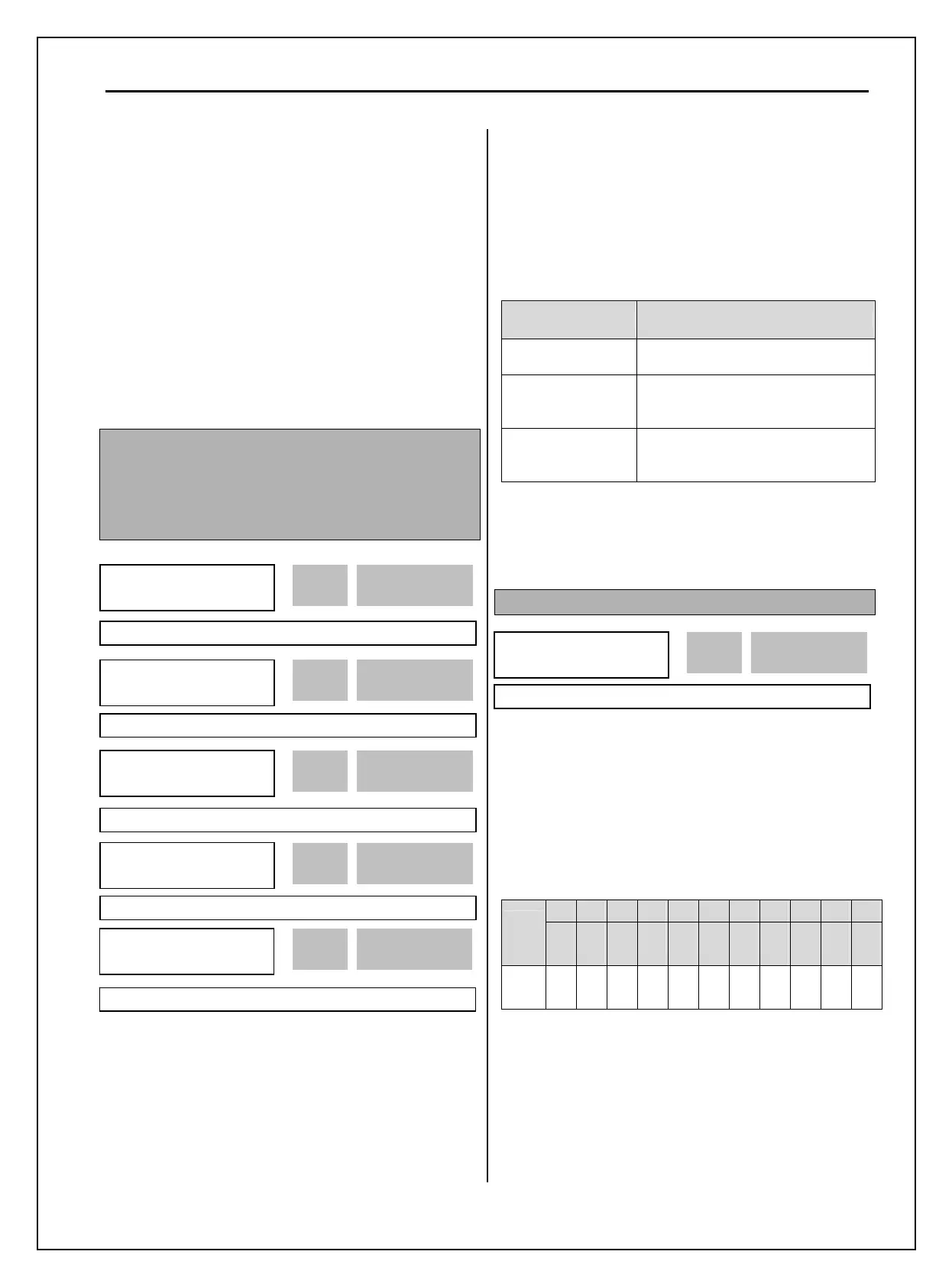
Three types of operating method described on the
table below are settable after loss of communication
signal.
Setting Range Description
None
Continuous operation after loss of
communication signal.
FreeRun
Inverter cuts off its output after
determining loss of communication
signal.
Stop
Inverter stops by its Decel pattern and
Decel time after determining
communication signal.
I/O-94 setting is for communication using 232-485
converter. It should be set properly according to 232-
485 converter specification.
I/O-95: Normal Open/ Normal Close select
The input contact logic (Normal Open-A
Contact/Normal Close-B Contact) for M1, M2, M3,
M4, M5, M6, M7, M8, P4, P5 and P6 can be
programmed in this code. P4, P5 and P6 are settable
only with Sub-board installed.
[LCD KEYPAD DISPLAY]
P6 P5 P4 M8 M7 M6 M5 M4 M3 M2 M1
Input
T/M
10
bit
9
bit
8
bit
7
bit
6
bit
5
bit
4
bit
3
bit
2
bit
1
bit
0
bit
0: NO
1: NC
0/1 0/1 0/1 0/1 0/1 0/1 0/1 0/1 0/1 0/1 0/1
I/O►
COM Lost Cmd
92 None
0 92
Factory Default: None 0
I/O►
COM Time Out
93 1.0 sec
1.0 93
Factory Default: 1.0 sec 1.0
I/O►
In No/NC Set
95 00000000000
0000
95
Factory Default: 00000000000 0000
I/O►
Inv No.
90 1
1 90
Factory Default: 1 1
I/O►
Baud rate
91 9600 bps
3 91
Factory Default: 9600 bps 3
I/O►
Delay Time
94 5
5 94
Factory Default: 5 ms 5

 Loading...


