6-1
CHAPTER 6 - PARAMETER DESCRIPTION
6.1 Drive group [DRV]
DRV-00: Command Frequency/ Output Current
(LCD)
1) Digital frequency setting
- When DRV-04 [Frequency Mode] is set to 0
(Keypad-1) or 1 (Keypad-2), command freq is
settable less than FU1-30 [Maximum Frequency].
2) Monitoring function setting
- Command frequency displayed during stop.
- Output current/frequency displayed during run.
Analog/digital frequency command source setting:
DRV-04 [Frequency Mode]
When DRV-04 [Frequency Mode] is set to V1, V1S,
I, V1+I or Pulse, frequency command is set via I/O-
01~16 [Analog Frequency command]. Refer to I/O-
01~16 for detail description.
When setting APP-02 [PID operation selection]
and/or APP-80 [Ext. PID operation select] to “Yes”,
I/O-86~88 parameter settings become available.
Changing I/O-86~88 value will affect all of the unit
display for reference values such as DRV-00 and I/O-
01~16. See the related parameter description on the
manual for more.
When APP-02 [PID operation selection] is set to
“Yes” with APP-04 [PID Aux speed selection] to
“No,” the selection made among
V1,V1S,I,V1+I,Pulse in DRV-04 [Freq mode]
becomes PID reference input value and PID target
output value becomes inverter reference frequency.
See the PID description on the manual for more.
Set APP-80 [Ext. PID operation selection] to “Yes”
and control terminal “I” to “4~20mA”, Ext. PID
feedback value. Set one of the I/O-20~27 to [Ext PID
Run]. When the selected terminal for [Ext PID Run]
is turned ON, Ext. PID operation begins and Ext. PID
output value becomes inverter command frequency.
See APP-80~97 for details.
When DRV-16 [Speed Unit Selection] is set to 1
(Rpm), Hz display is changed to Rpm.
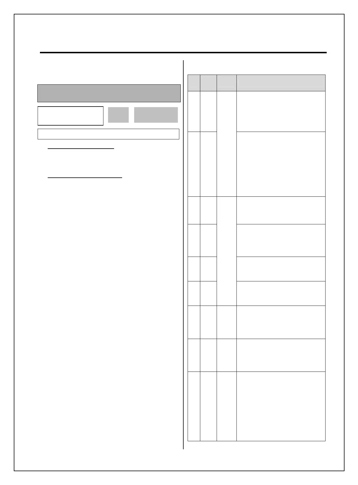
DRV-04 [Frequency Mode] setting guide
Set
DRV
-04
Name Programming Description
0
Key
Pad-1
1. In DRV-00, press the [PROG]
key.
2. Set the desired freq.
3. Press the [ENT] key to write the
new value into memory.
1
Key
Pad-2
Digital freq. command
1. In DRV-00, press the [PROG]
key.
2. Press the [
(Up)] or [(Down)]
key to set the desired freq. Speed is
reflected to the inverter real time
upon pressing the UP/DOWN keys.
3. Press the [ENT] key to write the
new value into memory.
2V1
Voltage analog input (0 to 12V) to
Control terminal “V1”.
See the description of I/O-01~05.
3V1S
Voltage analog input (-12 to 12V,
FWD/REV Run) to Control terminal
“V1”.
See the description of I/O-01~05.
4I
Current analog input (4 to 20mA) to
Control terminal “I”.
See the description of I/O-06~10.
5V1+I
Analog freq. command
0-10V/4-20mA Analog input
Control terminal “V1”,“I”.
See the description of I/O-01~10.
6Pulse
Pulse
command
Set the command frequency (0-
100kHz) from control input terminal
“A0 or B0”. See the I/O-11~16.
7
Int.
485
Communi-
cation
Set the command frequency using
RS485 (1200~19200bps) from “C+
or C-” control terminals. See the
I/O-90~93.
8
Ext.
PID
Ext.PID
Reference frequency
Set APP-80 [Ext PI Mode] to [Yes].
Apply 4~20mA {Ext.PID feedback
value} to control terminal “I”.
Set one of the I/O-20~27 to [Ext
PID Run].
When the defined terminal is ON,
inverter starts Ext.PID operation and
the Ext.PID output value becomes
inverter command frequency. See
APP-80~97 for more.
DRV
►
Cmd. Freq
00 0.00 Hz
0.00
F
Factory Default: 0.00 Hz 0.00