Chapter 6 - Parameter Description [I/O]
6-37
6.4 Input/Output Group [I/O]
I/O-00: Jump to Desired Code #
Jumping directly to any parameter code can be
accomplished by entering the desired code number.
This code is available only with LCD keypad.
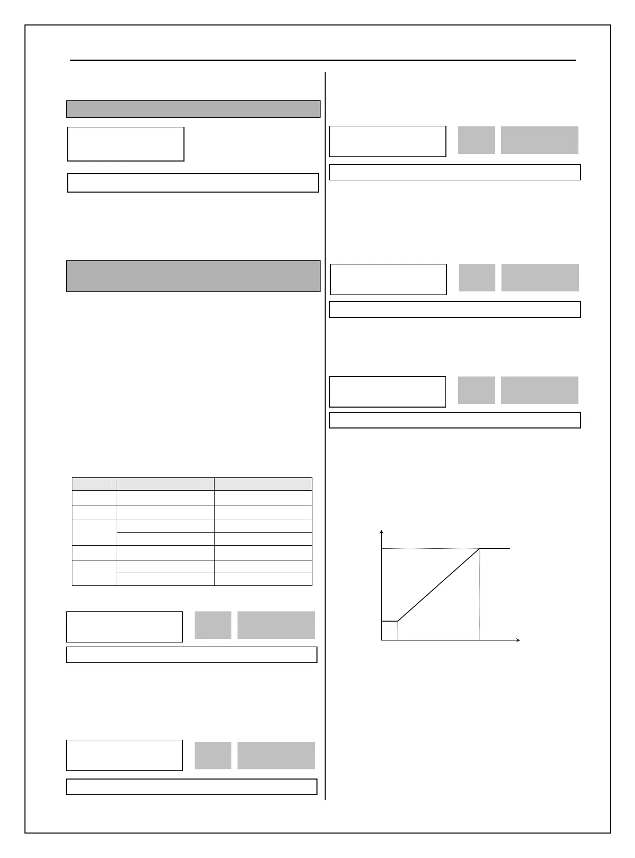
I/O-01 ~ I/O-05: Analog Voltage Input (V1) Signal
Adjustment
This is used to adjust the analog voltage input signal
when the frequency is referenced by the control
terminal ‘V1’. This function is applied when DRV-04
is set to ‘V1’, ‘V1S’, or ‘V1+I’. Reference frequency
versus Analog voltage input curve can be made by
four parameters of I/O-02 ~ I/O-04. User-selected
Unit appears in [**]. To change the unit, more than
one in APP-02 [PID operation selection] and APP-80
[Ext. PID operation selection] is set to “Yes” and
then select the desired unit Percent, Bar, mBar, kPa,
and Pa among in I/O-86 [V1 user unit selection].
Code Factory Default Setting Range
I/O-01 10 [msec] 0~9999 [msec]
I/O-02
0 [V] 0 ~ 12 [V]
0 [Hz] 0 ~ Max Freq
I/O-03
0 [**] 0 ~ 100.00 [**]
I/O-04
10 [V] 0 ~ 12 [V]
60 [Hz] 0 ~ Max Freq
I/O-05
0 [**] 0 ~ 100.00 [**]
This is the filtering time constant for V1 signal input.
Increase this value if the V1 signal is affected by
noise causing unstable operation of the inverter.
Increasing this value makes response time slower.
This is the minimum voltage of the V1 input at which
inverter outputs minimum frequency.
This is the inverter output minimum frequency (or
target value) when there is the minimum voltage
(I/O-02) on the V1 terminal.
This is the maximum voltage of the V1 input at
which inverter outputs maximum frequency.
This is the inverter output maximum frequency (or
target value) when there is the maximum voltage
(I/O-03) on the V1 terminal.
[Reference Frequency vs Analog Voltage Input (0 to 12V)]
I/O
►
Jump code
00 1
Factory Default: 1
I/O►
V1 filter
01 10 ms
10 01
Factory Default: 10 ms 10
I/O►
V1 volt x1
02 0.00 V
0.00 02
Factory Default: 0.00 V 0.00
I/O►
V1 freq y1
03 0.00 Hz
0.00 03
Factory Default: 0.00 Hz 0.00
Factory Default: 10.00 V 10.00
I/O►
V1 freq y2
05 60.00 Hz
60.00 05
Factory Default: 60.00 Hz 60.00
Reference Frequency
I/O-05
V1 terminal
(0~12V)
I/O-03
I/O-02 I/O-04
I/O►
V1 volt x2
04 0.00 V
10.00 04

 Loading...


