Chapter 6 - Parameter Description [I/O]
6-42
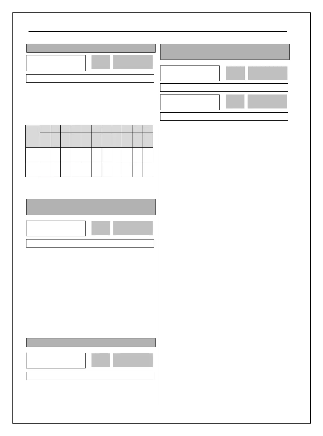
I/O-28: Terminal Input Status
This code displays the input status of control
terminals M1-M8, P4-P6. P4, P5, P6 will be only
displayed and used when the sub-board is installed.
[LCD Keypad Display]
P6 P5 P4 M8 M7 M6 M5 M4 M3 M2 M1
Input
T/M
10
bit
9
bit
8
bit
7
bit
6
bit
5
bit
4
bit
3
bit
2
bit
1
bit
0
bit
OFF
status
0 0 0 0 0 0 0 0 0 0 0
ON
status
1 1 1 1 1 1 1 1 1 1 1
I/O-29: Programmable Digital Input Terminal filter
time constant
Set the responsiveness of input terminals M1-M8 and
P4-P6. It is effective when noise level is high.
Increasing this will make response time slower and
decreasing faster.
Note: Set it higher than 100msec at Inverter-
commercial line exchange operation. This will be
useful to prevent chattering and momentary
malfunction.
I/O-30: Jog Frequency
This code sets the jog frequency. See I/O-31~42,
DRV-05~ 07 for details.
I/O-31~42: Step Frequency 4, 5, 6, 7, 8, 9, 10, 11,
12, 13, 14, 15
□
□
□
[Speed-L, Speed-M, Speed-H, Speed-X]
By setting M1, M2, M3 terminals to ‘Speed-L’,
‘Speed-M’ and ‘Speed-H’ respectively, inverter can
operate at the preset frequency set in DRV-05 ~
DRV-07 and I/O-20 ~ I/O-27.
The step frequencies are determined by the
combination of M1, M2 and M3 terminals as shown
in the following table.
I/O►
Step freq-4
31 40.00 Hz
40.00 31
Factory Default: 40.00 Hz 40.00
I/O►
Step freq-5
32 50.00 Hz
50.00 32
Factory Default: 50.00 Hz 50.00
I/O►
In status
28 00000000000
0000 28
Factory Default: 00000000000 0000
I/O►
Jog freq
30 10.00 Hz
10.00 30
Factory Default: 10.00 Hz 10.00
I/O►
Ti Filt Num
29 15 ms
15 29
Factory Default: 15 ms 15