Chapter 6 - Parameter Description [DRV]
6-7
DRV-13: Motor Direction Set (7-Segment Keypad)
This code sets the motor direction when using the 7-
Segment keypad.
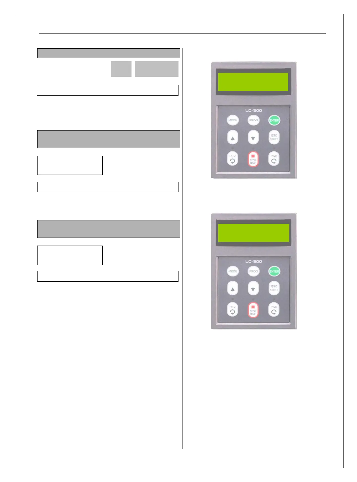
DRV-14: Command/Output Frequency Display
(LCD Keypad)
This code shows the Command (Target) Frequency
set in DRV00 and inverter Output Frequency.
DRV-15: Reference/Feedback Frequency Display
(LCD Keypad)
This code shows the Reference Frequency and
Feedback Frequency while PID operation.
Appears only when ‘Yes’ is selected in APP-02
Inverter PID controller’s reference and feedback
value are displayed. When APP-02 [PID operation
selection] is set to “YES,” reference and feedback
values are displayed in Hz. When APP-02 [PID
operation selection] is set to “YES,” and APP-06
[PID feedback selection] is set (one of the I, V1,
Pulse) and the desired unit is set in I/O-86 [V1 Unit
Sel], I/O-87 [I Unit Sel], I/O-88 [PulseUnitSel]
according to the selection in APP-06, PID reference
and feedback value will be displayed in user-selected
unit.
Ex1) When [mBar] is set
Ex2) When [kPa] is set
0 13
Factory Default: 0
DRV
►
TAR 0.00Hz
14
OUT 0.00Hz
Factory Default: 0.00Hz
DRV
►
REF 0.00Hz
15
FBK 0.00Hz
Factory Default: 0.00Hz
DRV
▶
REF 500.0mBa
15 FB
82.1mBa
DRV
▶
REF 500.0kPa