Chapter 7 - Troubleshooting & Maintenance
7-6
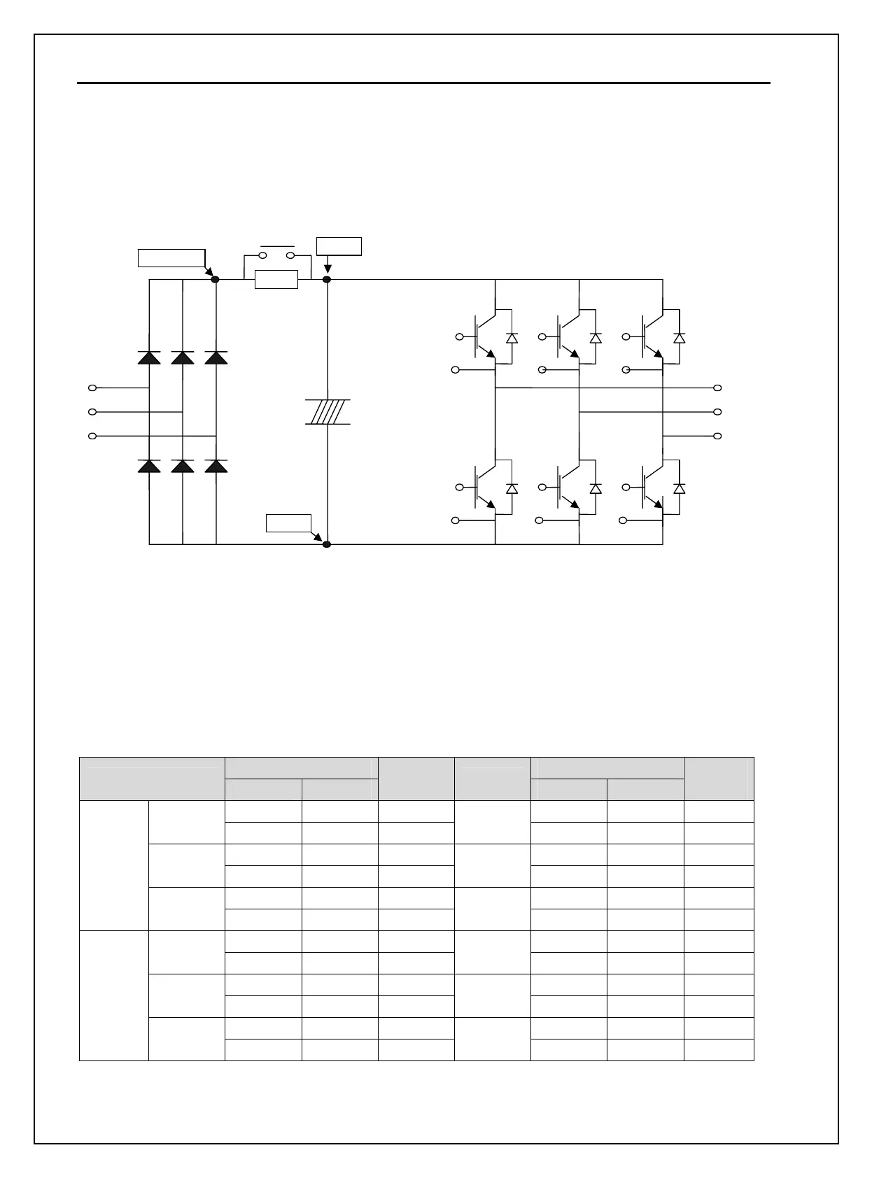
7.4 How to Check Power Components
1) Diode module and IGBT module check (5.5~ 30kW)
Before checking the power components, be sure to disconnect AC Input supply and wait until the Main
Electrolytic Capacitors (DCP-DCN) is discharged.
Turn the power off and disconnect RST/UVW wiring.
Determine whether inverter terminals (R,S,T, U, V, W, P1(or P2),N) are energized or not using a tester.
Wait until the Main Electrolytic Capacitors (DCP-DCN) is discharged to a safe level.
Enormous amount of value such as Mega will be displayed when Open. When closed, the resistance
value ranges from a few ohms to tens of Ω. Sometimes, it seems to be closed due to electrolytic
capacitors but soon to be displayed mega value resistance.
The displayed value is not always the same according to modules and tester types but should be similar.
Modules number and checking point
Test polarity Test polarity
Module
+ -
Check
value
Number
+ -
Check
value
R DCP+ Closed R N Open
D1
DCP+ R Open
D4
N R Closed
S DCP+ Closed S N Open
D2
DCP+ S Open
D5
N S Closed
T DCP+ Closed T N Open
Diode
D3
DCP+ T Open
D6
N T Closed
U DCP Closed U N Open
Tr1
DCP U Open
Tr4
N U Closed
V DCP Closed V N Open
Tr3
DCP V Open
Tr6
N V Closed
W DCP Closed W N Open
IGBT
Tr5
DCP W Open
Tr2
N W Closed
Charge resistor
M/C
R
S
T
U
W
D1
+
Electrolytic
capacitors
DCP
N
Tr3
Tr6
Tr5
Tr2
Tr1
Tr4
DCP+
D2 D3
D4 D5 D6

 Loading...


