Chapter 6 - Parameter Description [FU2]
6-30
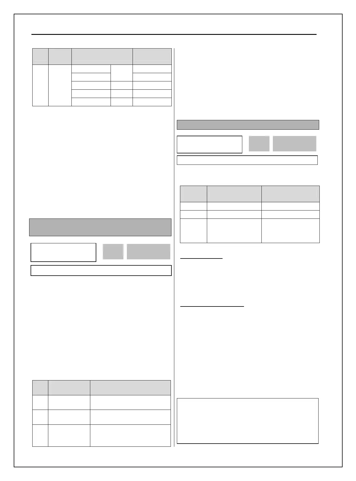
Code
LCD
Display
Factory Default Setting range
5.5 ~ 22 kW 0.7 ~ 15 [kHz]
30 kW
5 [kHz]
0.7 ~ 10 [kHz]
37 ~ 75 kW 4 [kHz] 0.7 ~ 4 [kHz]
90 ~ 280 kW 3 [kHz] 0.7 ~ 3 [kHz]
FU2-
48
Carrier
freq
315 ~ 450 kW 2 [kHz] 0.7 ~ 2 [kHz]
This parameter affects the audible sound of the motor,
noise emission from the inverter, inverter
termperature, and leakage current. If the ambient
temperature where the inverter is installed is high or
other equipment may be affected by potential inverter
noise, set this value lower. If set above 10kHz,
reduce the rated current by 5% per 1kHz. Setting
Carrier freqeuncy set below 1.5 [kHz] when the FU2-
60 [Control mode selection] is set to Sensorless, the
control performance could be weaken.
☞ Caution: FU2-48 [Carrier freq] setting range
varies as inverter capacity.
FU2-49: PWM Mode Selection (to reduce noise or
leakage current by changing PWM method)
Noise and leakage current can be reduced without
changing carrier freqeuncy by decreasing switching
cycle.
“Normal 1” is the general PWM method while
“Normal 2” is the PWM method when low noise (low
motor sound) is needed at motor starting. When
Normal 1 is selected at motor starting, inverter
changes switching frequency from low to set value.
When Normal 2 is selected, inverter starts to operate
at the set-value. “Low Leakage” is used to reduce
Leakage current by decreasing switching cycle.
No
I/O-86,-87,-
88 setting
Description
0 Normal 1
Operation via basic
Carrier(switching) frequency.
1 Normal 2
Operation via fixed
Carrier(switching) frequency.
2 Low Leakage
Change (Carrier)switching
frequency pattern to reduce
leakage current.
☞ Caution: Reducing the Carrier frequency may
increase noise.
☞ Caution: When 2 {Low leakage} is selected
while carrier frequency is set lower than 2.0 kHz
in FU2-48, FU2-48 value is automatically set to
2.0kHz.
FU2-60: Control mode selection
Selects the control mode of the inverter
FU2-40
setting
LCD Display Description
0 V/F V/F Control
1 Slip compensation Slip compensation
2 Sensorless
Sensorless vector
control speed
operation
◈ V/F control:
This parameter controls the voltage/frequency ratio
constant. It is recommended to use the torque boost
function when a greater starting torque is required.
Related function: FU1-67~69 [Torque boost]
◈ Slip compensation:
This function is used to maintain constant motor
speed. To keep the motor speed constant, the output
frequency varies within the limit of slip frequency set
in FU2-42 according to the load current. For example,
when the motor speed decreases below the reference
speed (frequency) due to a heavy load, the inverter
increases the output frequency higher than the
reference frequency to increase the motor speed. The
inverter increases or decreases the output by delta
frequency shown below.
FU2
►
Control mode
60 V/F
0 60
Factory Default: V/F 0
Delta freq (Slip Comp. Freq.) = Motor Rated slip *
(Output current - Motor No load current) / (Motor rated
current - Motor No load current)
Output freq = Reference freq + Delta freq
FU2
► PWM Select
49 Normal 1
0 49
Factory Default: Normal 1 0