Chapter 7 - Troubleshooting & Maintenance
7-8
7.5 Maintenance
The iP5A series is an industrial electronic product with advanced semiconductor elements. However,
temperature, humidity, vibration and aging parts may still affect it. To avoid this, it is recommended to perform
routine inspections.
7.5.1 Precautions
☞ Be sure to remove the drive power input while performing maintenance.
☞ Be sure to perform maintenance only after checking that the bus has discharged (The voltage between
terminal P1-N (or P2-N) should be less than DC 30V). The bus capacitors in the electronic circuit can still be
charged even after the power is turned off.
☞ The correct output voltage can only be measured by using a rectifier voltage meter. Other voltage meters,
including digital voltage meters, are likely to display incorrect values caused by the high frequency PWM
output voltage of the drive.
7.5.2 Routine Inspection
☞ Be sure to check the following before operation:
☞ The conditions of the installation location
☞ The conditions of the drive cooling
☞ Abnormal vibration
☞ Abnormal heating
7.5.3 Periodic Inspection
☞ Are there any loose bolt, nut or rust caused by surrounding conditions? If so, tighten them up or replace
them.
☞ Are there any deposits inside the drive-cooling fan? If so, remove using air.
☞ Are there any deposits on the drive’s PCB (Printed Circuit Boards)? If so, remove using air.
☞ Are there any abnormalities in the various connectors of the drive’s PCB? If so, check the condition of the
connector in question.
☞ Check the rotating condition of the cooling fan, the size and condition of the capacitors and the connections
with the magnetic contactor. Replace them if there are any abnormalities.
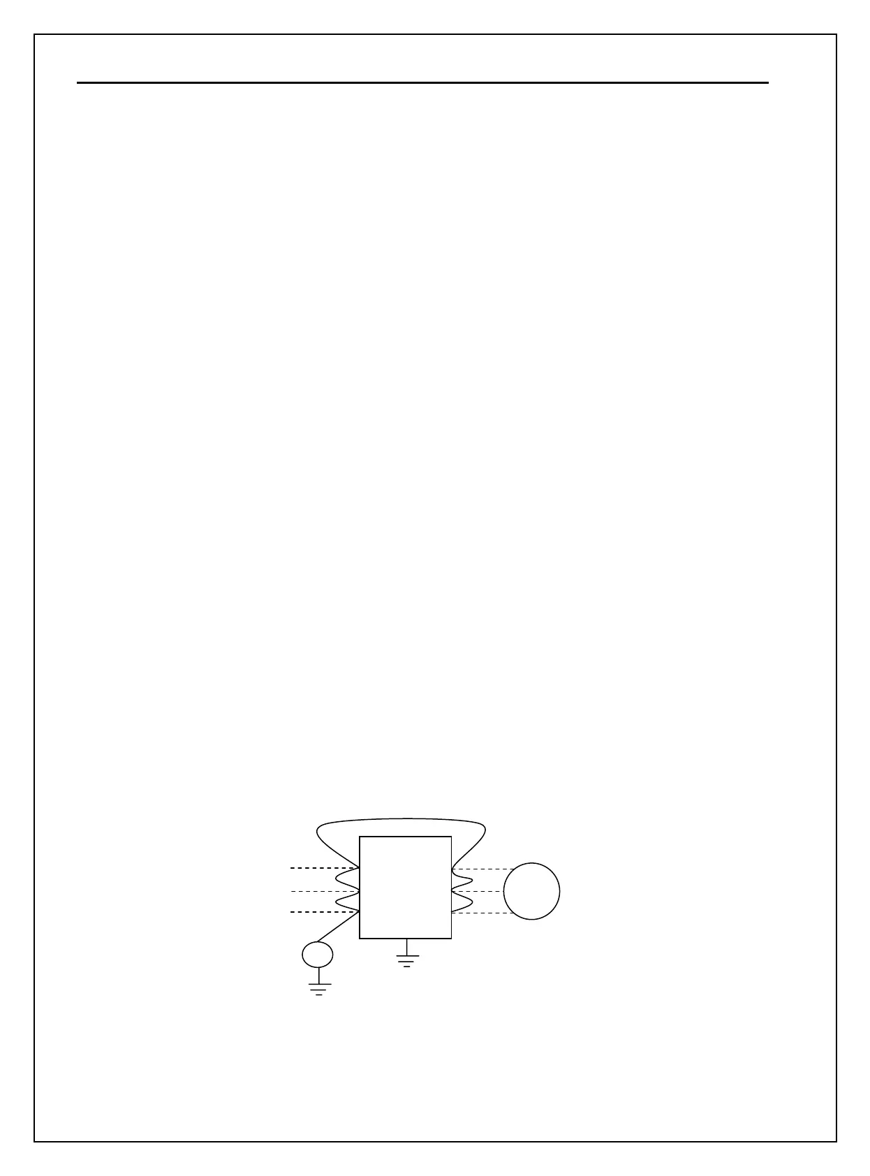
7.5.4 Megger/Dielectric Test
Perform megger test after inverter wiring is disconnected. Test voltage should not be applied to the inverter.
Megger test should be conducted only for the main circuit, not the control circuit. Use DC 500V megger.
Dielectric test should not be conducted to the inverter. Otherwise, IGBT may be damaged.
U
V
W
INVERTER
R
S
T
AC
GND
DC500V
M