Chapter 9 – RS485 Communication
9-3
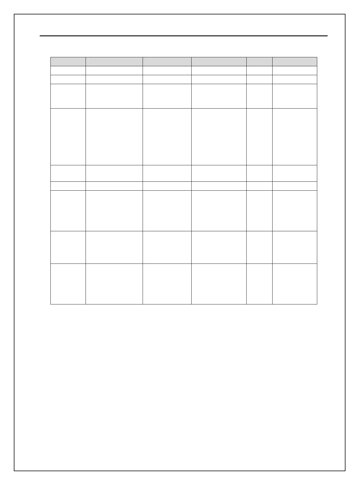
▣ Communication parameters
Code Display Name Set value Unit Default
DRV_03 Drive mode Drive mode Int. 485 Fx/Rx-1
DRV_04 Freq mode Freq mode Int. 485 KeyPad-1
DRV_91 Drive mode2 Drive mode 2
KeyPad
Fx/Rx-1
Fx/Rx-2
Fx/Rx-1
DRV_92 Freq mode2 Freq mode 2
KeyPad-1
KeyPad-2
V1
V1S
I
V1+I
Pulse
KeyPad-1
I/O_20~27 M1 ~ M8
Programmable
Digital Inputs
Main-drive
I/O_90 Inv No Inverter number 1~250 1
I/O_91 Baud rate
Communication
speed
1200 bps
2400 bps
4800 bps
9600 bps
19200 bps
9600 bps
I/O_92 COM Lost Cmd
Operating mode
when
communication
signal is lost
None
FreeRun
Stop
None
I/O_93 COM Time Out
Time to
determine
whether
Communication
signal is lost.
0.1~120.0 sec 1.0
9.3 Operation
9.3.1 Operating steps
1) Check whether the computer and the inverter are connected correctly.
2) Turn ON the inverter. But, do not connect the load until stable communication between the computer and the
inverter is verified. Start the operating program for the inverter from the computer.
3) Operate the inverter using the operating program for the inverter.
4) Refer to “13.8 Troubleshooting” if the communication is not operating normally.
5) User program or the “DriveView” program supplied from LS Industrial Systems can be used as the operating
program for the inverter.
6) Turn the inverter J3 switch ON to connect the terminating resistor for the end of network.
* Connect to C+,C-,CM terminal on the control terminal. Be careful for the polarity(+, -).
* Max connectable inverter is 31.

 Loading...


