Chapter 6 - Parameter Description [I/O]
6-51
[Steady]
AX-CX is CLOSED when the inverter is running at
constant speed.
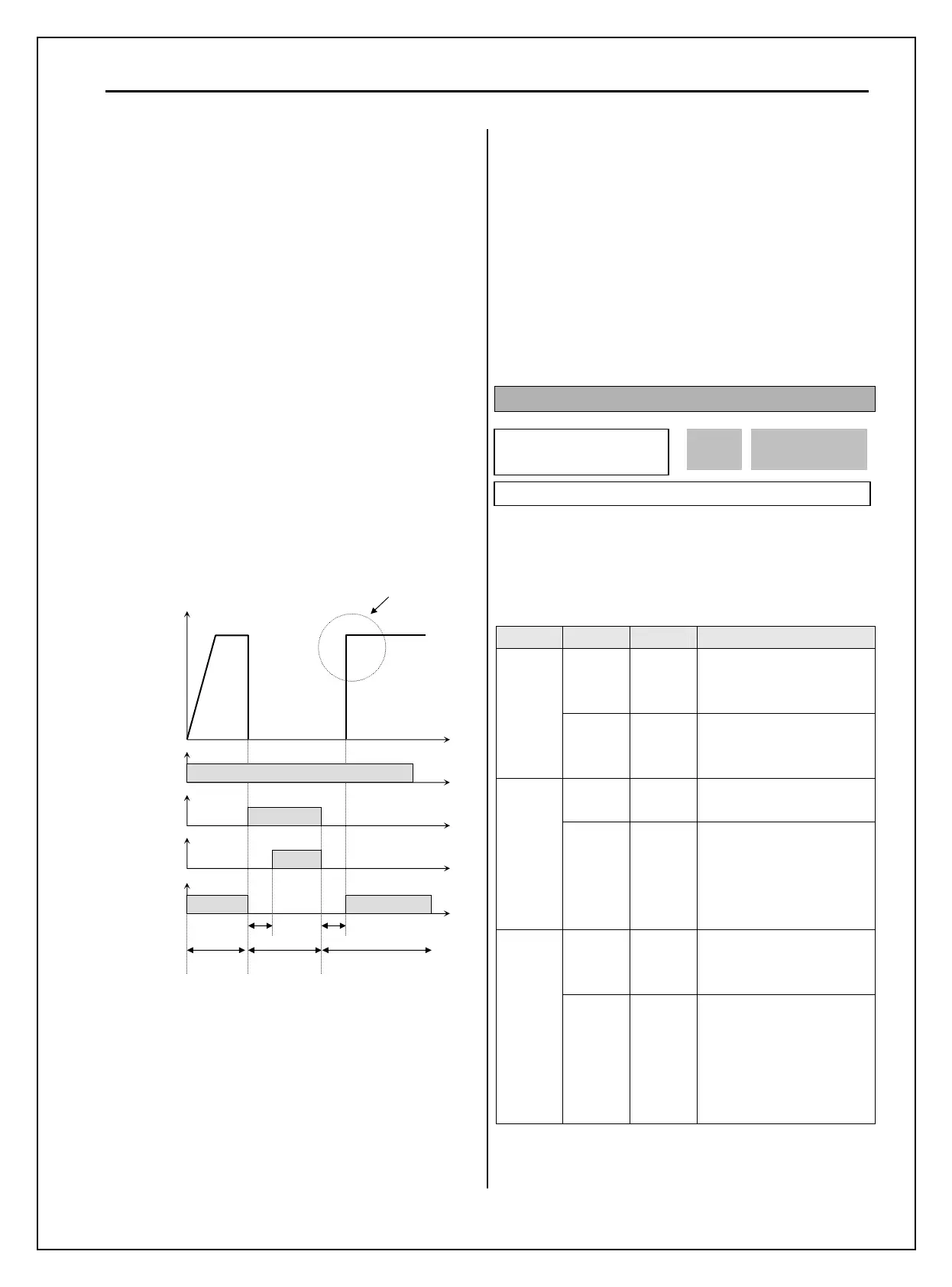
[INV line, COMM line]
This function is used in conjunction with ‘Exchange’
function of Programmable digital input for
commercial line exchange.
The following three conditions should be set:
1) Define one of the Programmable digital input
terminals to “Exchange”.
2) Define one of the Programmable digital output
terminals to “INV line”.
3) Define one of the Programmable digital output
terminals to “COMM line”.
Note: Set I/O-29 above 100 msec at Exchange
operation. This helps to prevent chattering and
momentary malfunction.
[AX-CX configured as ‘COMM line’,
‘Exchange’ and INV line’]
[Ssearch]
AX-CX is CLOSED during the inverter is speed
searching.
[Ready]
AX-CX is CLOSED when the inverter is ready to run.
[MMC]
Automatically set to ‘MMC’ when ‘MMC’ is
selected in APP-01.
I/O-80: Fault Output Relay (3A, 3B, 3C)
This function is used to allow the fault output relay to
operate when a fault occurs. The output relay
terminal is 3A, 3B, 3C where 3A-3C is a normally
open contact and 3B-3C is a normally closed contact.
Bit Setting Display Description
0 000
Fault output relay does
not operate at ‘Low
voltage’ trip.
Bit 1
(LV)
1 001
Fault output relay
operates at ‘Low voltage’
trip.
0 000
Fault output relay does
not operate at any fault.
Bit 2
(Trip)
1 010
Fault output relay
operates at any fault
except ‘Low voltage’ and
‘BX’ (inverter disable)
fault.
0 000
Fault output relay does
not operate regardless of
the retry number.
Bit 3
(Retry)
1 100
Fault output relay
operates when the retry
number set in FU2-26
decreases to 0 by faults.
Disabled while Auto retry
is ON.
When several faults occurred at the same time, Bit 1 has
the first priority. (Active order: Bit 1->Bit 2->bit3)
I/O►
Relay mode
80 010
010 80
Factory Default: 010 010
‘Exchange’
FX-CM
ON
Output Frequency
Time
Time
ON
Time
‘COMM line’
ON
Time
ON
Time
ON
t1 t2
Inverter
Drive
Inverter
Drive
Commercial
Line Drive
t1, t2: 500msec (interlock time)
Speed Search
‘INV line’

 Loading...


