Chapter 6 - Parameter Description [DRV]
6-2
I/O-01~05 [Frequency command setting via Analog
Voltage Input “ V1”]
Command Freq. setting via “V1” input terminal when
set DRV-04 [Frequency mode] to V1, V1S, or V1+I.
A User-selected unit will be displayed in [**] when
one of the APP-02[PID operation selection] and
APP-80 [Ext. PID operation selection] is set to
“Yes,” and set the desired unit among Percent, Bar,
mBar, kPa, Pa in I/O-86 [Voltage input user unit
selection].
Code Default Setting range
I/O-01
10 [msec] 0 ~ 9999 [msec]
I/O-02
0 [V] 0 ~ 12 [V]
0 [Hz] 0 ~ Max. freq
I/O-03
0 [**] 0~100.00[**]
I/O-04
10 [V] 0 ~ 12 [V]
60 [Hz] 0 ~ Max freq
I/O-05
0 [**] 0~100.00[**]
Code
LCD
Display
Parameter Name
I/O-01
V1 filter Filter Time Constant for V1 Input
I/O-02
V1 volt x1 V1 Input Minimum Voltage
V1 freq y1
Frequency Corresponding to V1
Input Minimum Voltage
I/O-03
V1[**]y1
Target value Corresponding to V1
input minimum voltage.
I/O-04
V1 volt x2 V1 Input Maximum Voltage
V1 freq y2
Frequency Corresponding to V1
Input Maximum Voltage
I/O-05
V1[**]y2
Target value Corresponding to V1
input maximum voltage.
Important: Increase I/O-01 [Filter Time Constant
for V1 Input] if the V1 signal is affected by noise
causing unstable operation. Increasing this value
makes response time slower.
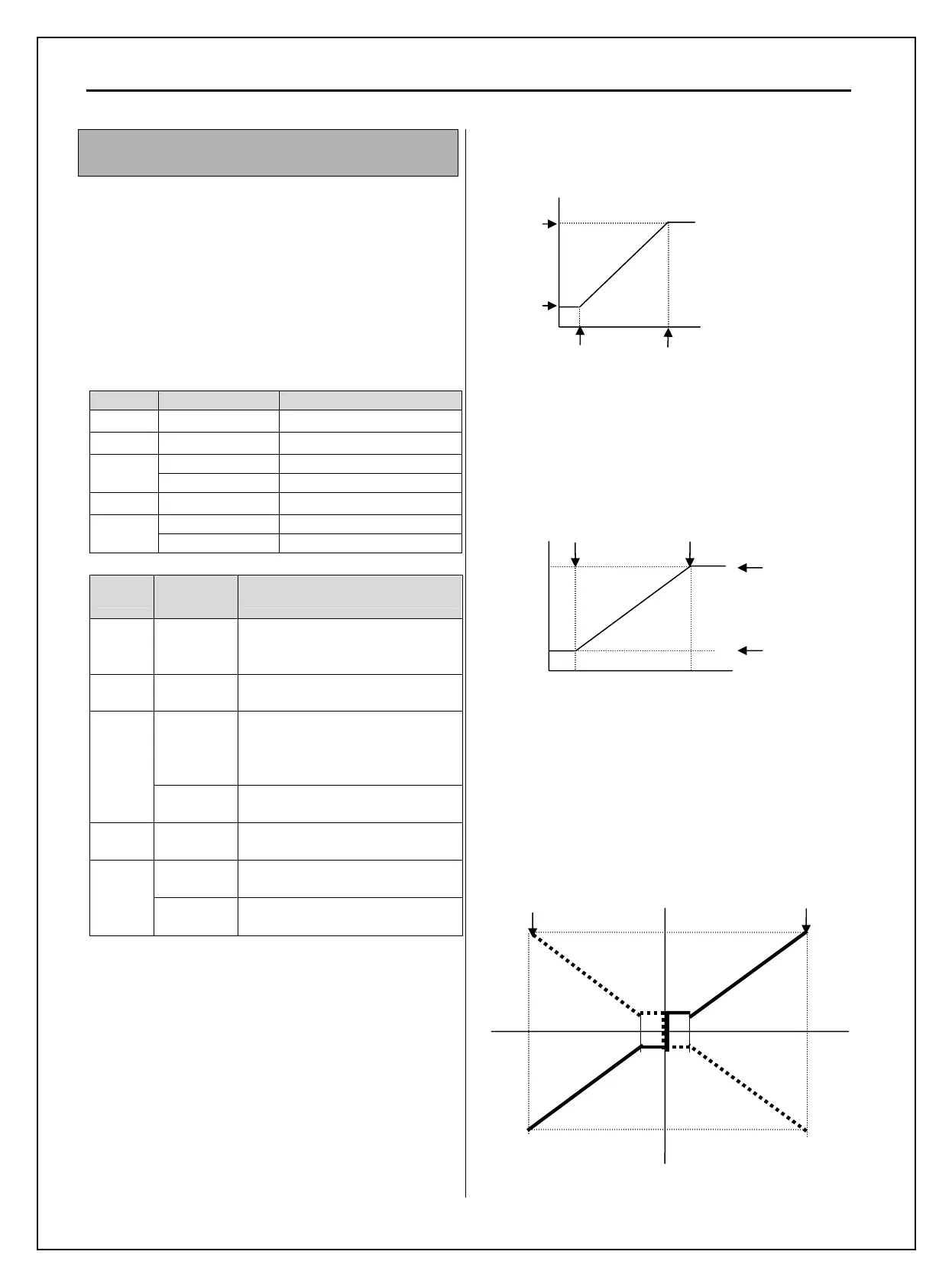
In the case of 0~12V V1 voltage input
In the case of –12~12V V1 voltage input
Setting for Bi-polarity and the uni-polarity is the
same as the graph above. Set the positive value for
Voltage and frequency and negative value is
symmetrical of positive setting. The following graph
shows the relationship between voltage input and
direction command (Positive/Negative).
V1 analog input
(0~12V)
Set freq.
(target value)
I/O-02
V1 Min
Voltage
I/O-03
I/O-05
I/O-04
V1 Max
Voltage
V1 terminal (0~12 V)
Set freq
(target value)
I/O-02
V1 Min voltage
I/O-03
I/O-05
I/O-04
V1 Max voltage
Reverse
Max Freq
V1 (-12 ~ 12V)
Set freq (target value)
Rev
Forward
Max Freq
Fwd
- 12V
12