Chapter 6 - Parameter Description [APP]
6-68
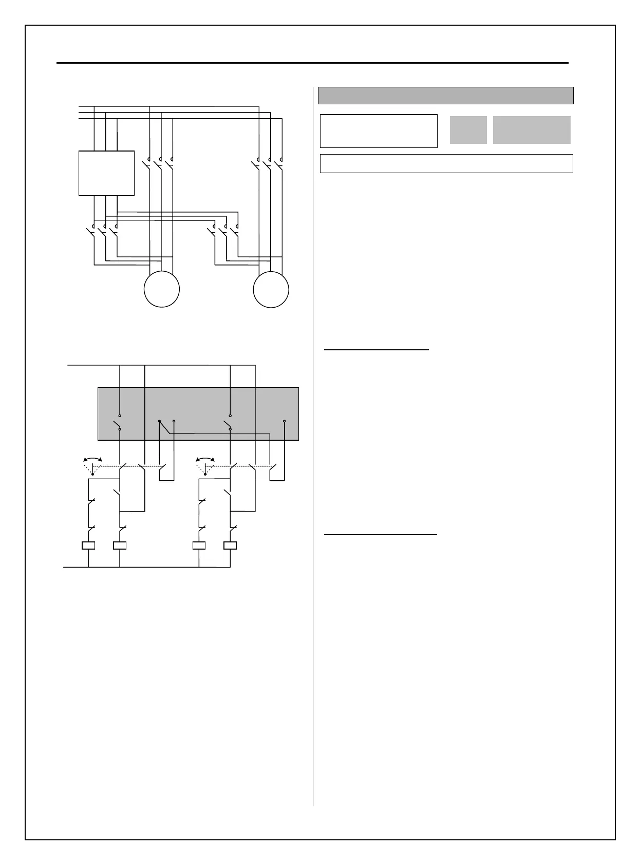
[Wiring Diagram for Inter-Lock Configuration]
[Sequence Circuit for Inter-Lock Configuration]
APP-69: Interlock Selection
When APP-69 [Interlock selection] is set to “Yes”,
M1~M4 can be used as the same activating condition
for AX1~AX4. Programmable digital input terminals
are activated when turned ON. If one of them are
turned Off, all motors will start running except the
motor connected to the off terminal. If the input
signal is turned off in the midst of running, inverter
stops all the motors and restarts the operation with
normal active motors.
Interlock during Stop
When Run signal is input during Stop, MMC
operation is started with the Aux motors(Relays)
turned ON.
Ex) When Interlock is not selected:
RLY1RLY2RLY3RLY4
When Interlock is active (the terminal defined
as Interlock/RLY2 is turned Off):
RLY1 RLY3RLY4
Interlock during RUN
When Interlock is active during RUN (the terminal
defined as interlock/RLY is turned Off during RUN),
inverter stops all motors and restart MMC operation
with aux motors except the interlocked one(terminal
turned Off).
Ex)Normal operation:
RLY1RLY2RLY3RLY4
When Interlock is active (the terminal defined as
Interlock/RLY3 is turned OFF), all Aux motors are
turned Off and stopped. MMC operation is restarted
except Aux motor 3 (RLY 3 Off).
Aux motors start rotating in the order of
RLY1RLY2RLY4.
3 Phase
Input
K1
K1.1
K2
K2.2
U V W
R S T
iP5A
M1
M2
230VA
iP5A
M1/iP5 M2/iP5
M1/main
K1
K1.1
K2
K2.1
K2.1
K1
K1
K2
Auto
Auto
Main
Main
RLY RLY
M1
M2
CM
S1 S2
APP
►
Inter-lock
69 No
0 69
Factory Default: No 0