Chapter 3 - Installation
3-12
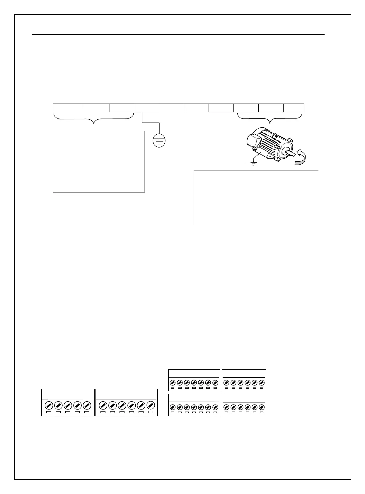
Power and Motor Connection Example (5.5~30kW inverters)
R(L1) S(L2) T(L3) G P1(+) P2(+) N(-) U V W
3.2.4 Control circuit wiring
1) Wiring Precautions
CM and 5G terminals are insulated each other. Do not connect these terminals together or to the power
ground.
Use shielded wires or twisted wires for control circuit wiring, and separate these wires from the main power
circuits and other high voltage circuits (200V relay sequence circuit).
It is recommended to use the cables of 0.0804mm
2
(28 AWG) ~ 1.25mm
2
(16 AWG) for TER1, TER2
control terminals and the cables of 0.33mm
2
(22 AWG) ~ 2.0mm
2
(14 AWG) for TER3, TER4 control
terminals.
2) Control terminal layout
Power supply must be
connected to the R(L1), S(L2),
and T(L3) terminals.
Connecting it to the U, V, and
W terminals causes internal
damages to the inverter.
Arranging the phase sequence is
Motor should be connected to the U, V,
and W terminals.
If the forward command (FX) is on, the
motor should rotate counter clockwise when
viewed from the load side of the motor. If
the motor rotates in the reverse, switch the U
Ground
r
n
Forward
A0
B0
5G
5G S0
S1
V+
V1
5G
V- I
NT
C+
CM
C-
M6 24
M7
M8
M1
CM
M2
M3 24
M4
M5
3A 3C
3B A1 C1
A2 C2 A3 C3 A4 C4
TER4
TER3
TER2 TER1
0.33mm
2
(22 AWG) ~ 2.0mm
2
(14 AWG)
0.08