Chapter 6 - Parameter Description [APP]
6-63
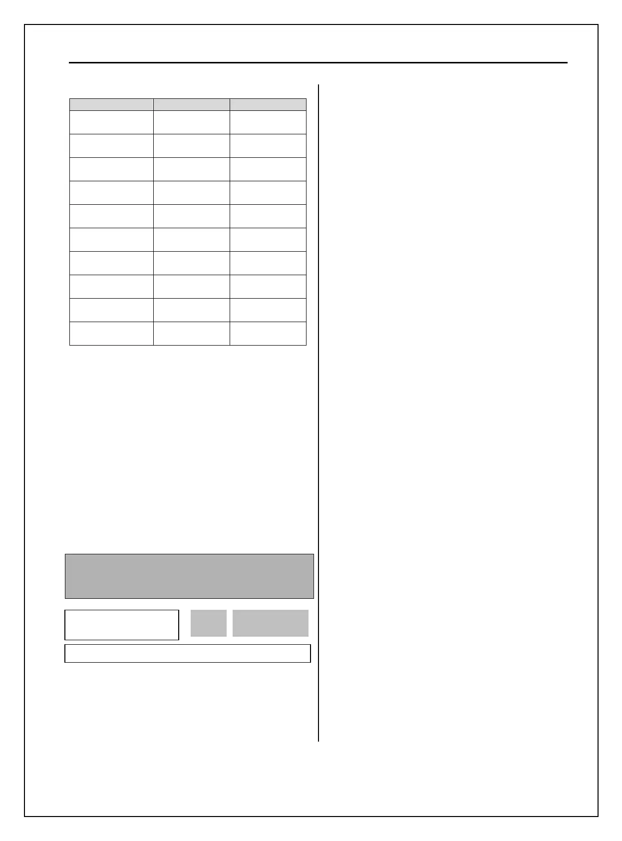
Description 1
st
Functions 2
nd
Functions
Acceleration time
DRV-01
[Acc. time]
APP-20
[2nd Acc time]
Deceleration time
DRV-02
[Dec. time]
APP-21
[2nd Dec time]
Base Frequency
FU1-31
[Base freq]
APP-22
[2nd BaseFreq]
Volts/Hz mode
FU1-40
[V/F Pattern]
APP-23
[2nd V/F]
Forward torque
boost
FU2-68
[Fwd Boost]
APP-24
[2nd F-boost]
Reverse torque
boost
FU2-69
[Rev Boost]
APP-25
[2nd R-boost]
Stall prevention
level
FU1-60
[Stall Level]
APP-26
[2nd Stall]
ETH level for 1
minute
FU1-61
[ETH 1min]
APP-27
[2nd ETH 1min]
ETH level for
continuous
FU1-62
[ETH cont]
APP-28
[2nd ETH cont]
Motor rated current
FU2-43
[Rated-Curr]
APP-29
[2nd R-Curr]
The 1
st
functions are applied if the assigned
multifunction terminal is not defined as ‘2nd Func’
nor ON. The 2
nd
function parameters are applied
when the multifunction input terminal set to ‘2nd
Func’ is ON. Parameters not listed on the table above
are same as the 1
st
function.
Note: Exchange the motor connection from the 1
st
motor
to the 2
nd
motor or the opposite when the motor is stopped.
Over voltage or over current fault may occur when the
motor is exchanged during operation.
Note:
The ‘User V/F’ function of FU1-40 [V/F Pattern] is
commonly used for the 1st and the 2nd motor.
APP-40: Number of Running Auxiliary Motor
Display
APP-40~APP-71: MMC Operation Control
This code shows how many auxiliary motors are run
by MMC control.
[MMC]: The ‘PID’ control should be selected in
APP-02 to use this function.
♦ One inverter can control multiple motors. This
function is often used when controlling the rate and
pressure of flow in fans or pumps. Built-in PI
controller controls a main motor after receiving
process control feedback value and keeps the control
value constant by connecting auxiliary motors to
commercial line when needed.
♦ In case that flow rate or flow pressure is beyond or
below the reference so the main motor cannot control
by itself, auxiliary motors are automatically turned
on/off. Maximum four (Aux.1-4 output) auxiliary
motors can be run. Each of Starting and Stop
Frequency should be set for automatically running
four auxiliary motors.
♦ Auto Change can be selected to automatically
switch the order of the running motors for keeping
motor run-time constant. Set mode ‘1’ for automatic
changing of auxiliary motors only and set mode ‘2’
for automatic changing of all motors including main
motor. For mode ‘2’, APP-67/68 should be set and
external sequence (Refer to APP-20~29) should be
configured.
♦ Abnormal motor can be skipped from running by
using the Programmable digital input terminals (M1,
M2, M3, and M4). If a Programmable digital terminal
(M1, M2, M3 and M4) is opened, the inverter stops
all running motors and restarts operation with only
normal motors except the abnormal (Off) motor.
(Refer to APP-69)
♦ Sleep function is initiated when flow demand is
low. Inverter stops the motor when the motor runs
below Sleep Frequency after Sleep Delay Time.
While in the sleep state, inverter keeps monitoring
and initiates Wake-Up function when the real value
(feedback) of the controlling amount has decreased
below the Wake-Up level.
Note: Only one auxiliary motor can be connected with
AUX terminal on control terminal strip without using
MMC Option Board.
APP► Aux Mot Run
40 0
0 40
Factory Default: 0 0