Chapter 3 - Installation
3-14
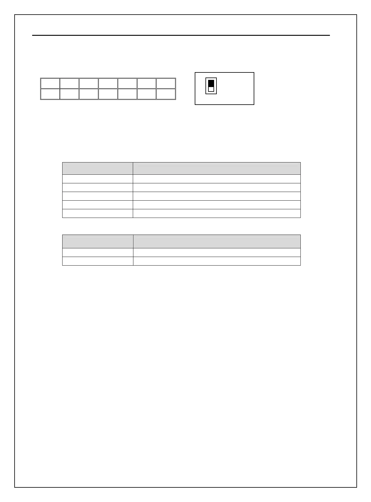
3.2.5 RS485 circuit wiring
Use C+ (RS485 signal High), C- (RS485 signal LOW) in TER 2. Turn the J3 switch ON (Upward) to connect the
termination resistor (120 ohm). J3 switch is on the left side of the TER2.
Item Specification
Transmission type Bus method, Multi drop Link System
Applicable inverter SV-iP5A series
Number of inverters Max.31
Transmission distance Within 1200m Max. (700m desired)
Recommendable cable 0.75mm
2
(18AWG), Shield Type Twisted-pair Wire
Item Specification
Installation C+, C-, CM terminals on the control terminal block
Power supply Insulated from the inverter power supply
3.2.6 Check points on wiring
1) Electrical or mechanical interlock of MC1 and MC2 is required for Inverter Bypass Operation. Otherwise,
chattering may occur or input power may flow to inverter output, damaging the inverter.
2) Make the sequence to disable the Auto restart after power failure if required. Otherwise, inverter will be
automatically restarted.
3) Do not apply the voltage directly to control circuit input terminals such as FX, RX.
C+ CM C- M6 24 M7 M8
M1 CM M2 M3 24 M4 M5
TER 2
J3
ON
OFF