Chapter 9 – RS485 Communication
9-4
9.4 Communication protocol (RS485)
The configuration of RS485 is that PC or PLC is the Master and Inverter Slave.
Inverter responds the Master’s Read/Write Requests.
When master sends Write Request to Inverter address # 255, all inverters perform Write action but do not return
a Acknowledge response. This is used to drive multiple inverters at the same time via RS485.
9.4.1 Basic format
1) Command message (Request):
ENQ Inverter No. CMD Data SUM EOT
1 byte 2 bytes 1 byte n bytes 2 bytes 1 byte
* Normal response (Acknowledge Response):
ENQ Inverter No. CMD Data SUM EOT
1 byte 2 bytes 1 byte
n * 4
bytes
2 bytes 1 byte
* Negative response (Negative Acknowledge Response):
ENQ Inverter No. CMD Data SUM EOT
1 byte 2 bytes 1 byte 2 bytes 2 bytes 1 byte
2) Description:
* Request starts with “ENQ” and ends with “EOT”.
* Acknowledge Response starts with “ACK” and ends with “EOT”.
* Negative Acknowledge Response starts with ”NAK” and ends with “EOT”.
* “Inverter Number” is the number of Inverters used and indicated in 2 byte ASCII-HEX.
(ASCII-HEX: Hexadecimal consists of ‘0’ ~ ‘9’, ‘A’ ~ ‘F)
* CMD: Capital letter (“IF Error” when small letter is used.)
Character ASCII-HEX Command
‘R’ 52h Read
‘W’ 57h Write
‘X’ 58h Request for monitoring
‘Y’ 59h Action for monitoring
Data: ASCII-HEX
Ex) when data value is 3000: 3000 (dec) → ‘0’ ’B’ ’B’ ’8’h → 30h 42h 42h 38h
Error code: ASCII (20h ~ 7Fh)
Receive/Send buffer size: Receive= 39 byte, Send=44 byte
Monitor register buffer: 8 Word
SUM: to check the communication error
SUM= ASCII-HEX format of lower 8 bit of (Inverter No. + CMD + DATA)
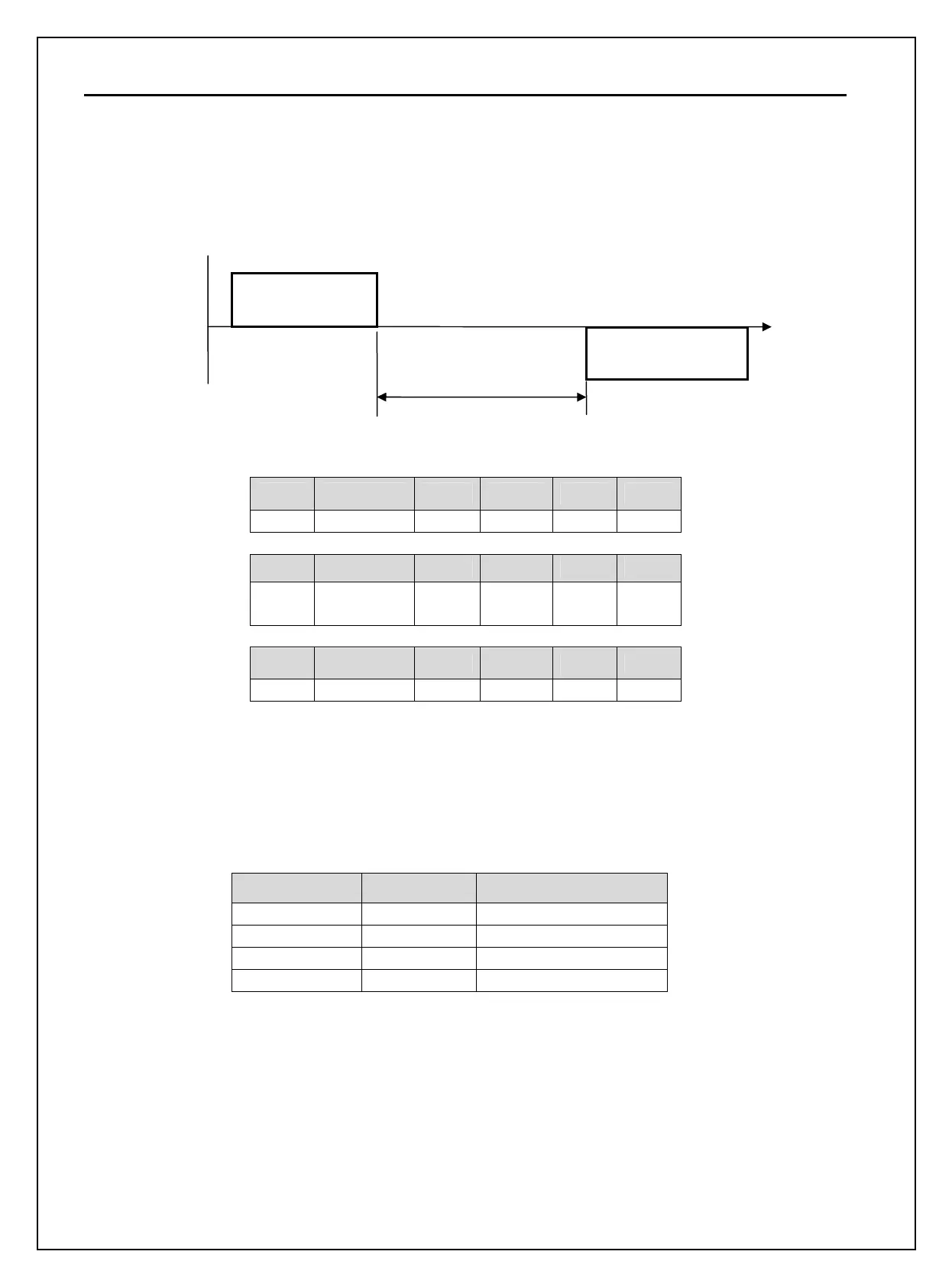
Request Frame
Response Frame
I/O 94 [Communication
response delay time]
Master
Slave
(Inverter)

 Loading...


