Chapter 6 - Parameter Description [DRV]
6-5
I
Apply the frequency reference
(4~20mA) to the “I” control terminal.
Refer to the I/O-06 to I/O-10 for
scaling the signal.
1+I
Apply the frequency reference
(0~12V, 4~20mA) to the “V1”,“I”
control terminals.
The ‘V1’ signal overrides the ‘I’
signal. See I/O-01~10.
PULSE
Set the freq command using “A0, B0”
terminals. Range: 0~100kHz. See I/O-
11~16.
Int. 485
Set the freq command using RS485
communication. See I/O-90~93.
Ext. PID
Set APP-80 [Ext PI Mode] to “Yes.”
Apply Ext. PID feedback value
“4~20mA” to control terminal “I”. Set
one of the I/O-20~27 to [Ext PID
Run]. Inverter starts Ext.PID operation
when the defined terminal is ON and
Ext.PID output value becomes inverter
command frequency. See APP-80~97
for details.
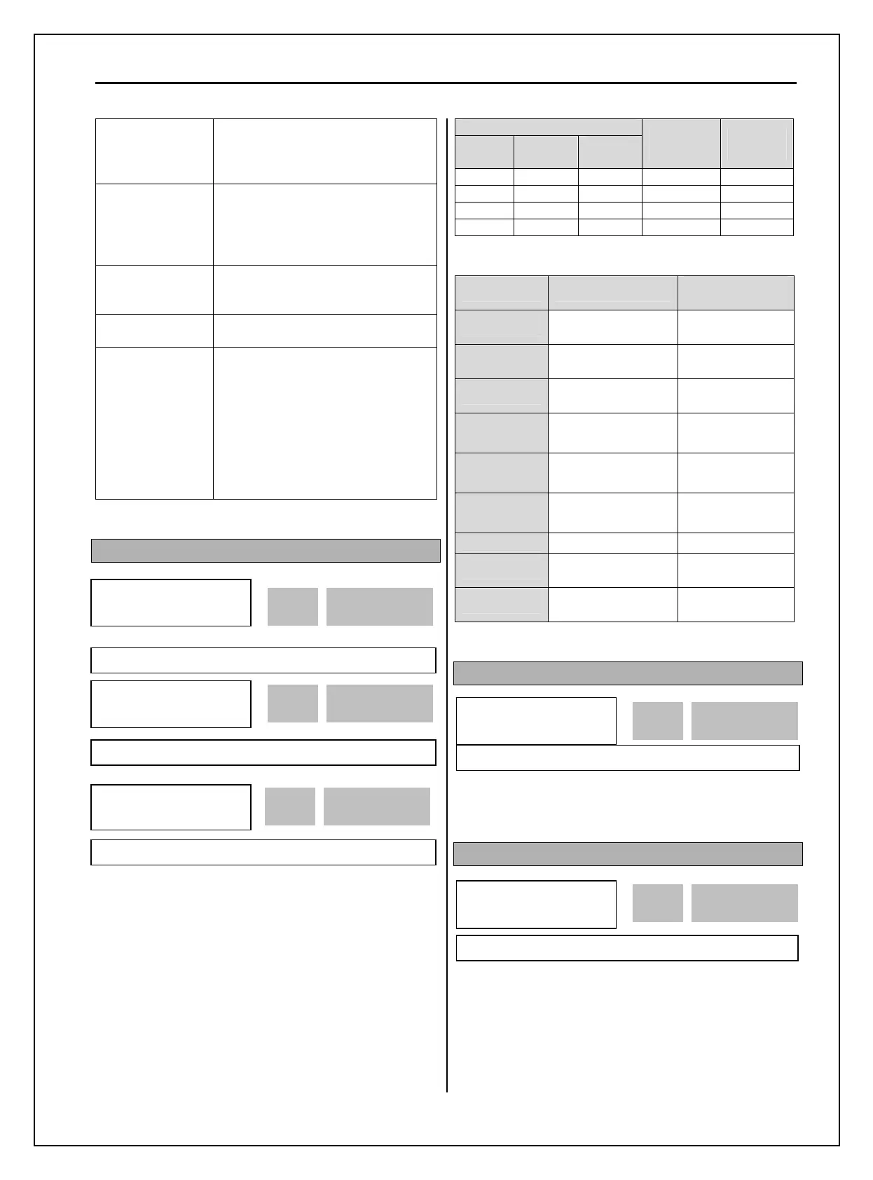
DRV-05 ~ DRV-07: Step Frequency 1 ~ 3
The inverter outputs preset frequencies set in these
codes according to the Programmable
Digital Input
terminals configured as ‘Speed-L’, ‘Speed-M’,
‘Speed-H’ and ‘Speed-X’. The output frequencies are
decided by the binary combination of M1~M8. The
frequency setting method of ‘Speed 0’ is decided by
DRV-04.
See I/O-21~27 description for Step Freq 4~7.
Binary Input Combination
Speed-
L
Speed-
M
Speed-
H
Output
Frequency
Step
Speed
0 0 0 DRV-00 Speed 0
1 0 0 DRV-05 Speed 1
0 1 0 DRV-06 Speed 2
1 1 0 DRV-07 Speed 3
Note: Speed 0 is the set value in DRV-04.
DRV-04 data DRV-00, 0 speed
Freq command
source
KeyPad-1
Digital command
freq
Keypad
KeyPad-2
Digital command
freq
Keypad
V1
Analog command
freq
Terminal
V1S
Analog command
freq
Terminal
I
Analog command
freq
Terminal
V1+I
Analog command
freq
Terminal
Pulse
Pulse command freq
Terminal
Int. 485
Comm. command
freq
Terminal
Ext. PID
Ext.PID reference
frequency
Keypad or
Terminal
DRV-08: Output Current
This code displays the output current of the inverter
in RMS.
DRV-09: Motor RPM
This code displays the motor speed in RPM while the
motor is running.
Use the following equation to scale the mechanical
speed using FU2-74 [Gain for Motor Speed display]
if you want to change the motor speed display to
rotation speed (r/min) or mechanical speed (m/min).
DRV
►
Step freq-1
05 10.00 Hz
10.00 05
Factory Default: 10.00 Hz 10.00
DRV
►
Step freq-2
06 20.00 Hz
20.00 06
Factory Default: 20.00 Hz 20.00
DRV
►
Step freq-3
07 30.00 Hz
30.00 07
Factory Default: 30.00 Hz 30.00
DRV
►
Current
08 0.0 A
0.0 08
Factory Default: 0.0 A 0.0
DRV
►
Speed
09 0rpm
0 09
Factory Default: 0rmp 0