Chapter 6 - Parameter Description [DRV]
6-3
To drive the motor in Forward direction, press FWD
key and apply 0-12V voltage as frequency command
or press REV key and apply –12~0V voltage as
frequency command. To drive the motor in Reverse
direction, press FWD key and apply –12~0V or press
REV key and apply 0~12V.
I/O-06~10 [Analog Current Input “I” Signal
adjustment]
Command Freq setting via “I” input terminal when
set DRV-04 [Frequency mode] to 3 (I) or 4 (V1+I)
A User-selected unit will be displayed in [**] when
one of the APP-02[PID operation selection] and
APP-80 [Ext. PID operation selection] is set to
“Yes,” and set the desired unit among Percent, Bar,
mBar, kPa, Pa in I/O-87 [Current input user unit
selection].
Code Default Setting range
I/O-06
10 [msec] 0 ~ 9999 [msec]
I/O-07
4 [mA] 0 ~ 20 [mA]
0 [Hz] 0 ~ Max. freq
I/O-08
0 [**] 0 ~ 100.00[**]
I/O-09
20 [mA] 0 ~ 20 [mA]
60 [Hz] 0 ~ Max. freq
I/O-10
0 [**] 0 ~ 100.00[**]
Code LCD display Parameter Name
I/O06
I filter
Filter time constant for I
signal Input
I/O-07
I curr x1 I Input Minimum Current
I freq y1
Frequency Corresponding
to I Input Minimum
Current
I/O-08
I [**] y1
Target value Corresponding to
I Input Minimum Voltage
I/O-09
I curr x2 I Input Maximum Current
I freq y2
Frequency Corresponding
to I Input Maximum
Current
I/O-1-0
I [**] y2
Target value Corresponding to
I Input Maximum Voltage
Important: Increase I/O-06 [Filter time constant for
I signal Input] if I signal is affected by noise causing
unstable operation. Increasing this value makes
response time slower.
DRV-01, 02: Accel/Decel Time 0
The inverter targets FU2-73 when accelerating or
decelerating. When FU2-73 is set to “Maximum
Frequency”, the acceleration time is the time taken by
the motor to reach FU1-30 from 0 Hz. The
deceleration time is the time taken by the motor to
reach 0 Hz from FU1-30 [Maximum Frequency].
When FU2-73 is set to “Delta Frequency”, the
acceleration and deceleration time is the time taken to
reach a target frequency (instead the maximum
frequency) from a specific frequency.
The acceleration and deceleration time can be
changed to a preset time via Programmable digital
inputs. By setting M1~M8 to ‘XCEL-L’, ‘XCEL-M’,
‘XCEL-H’ respectively, the 1~7 Accel and Decel
time set in I/O-50 to I/O-63 are applied by the binary
inputs of the M1~M8.
Note: Set the Accel time more than 0.5 sec for smooth
acceleration. Setting it too short may deteriorate the
starting performance.
In case of the inverters for 110~450kW(150~600HP), the
factory default of Accel/Decel Time is 60.0/90.0[sec]
respectively.
DRV
►
Acc. time
01 20.0 sec
20.0 01
Factory Default: 20.0 sec 20.0
DRV
►
Dec. time
02 30.0 sec
30.0 02
Factory Default: 30.0 sec 30.0
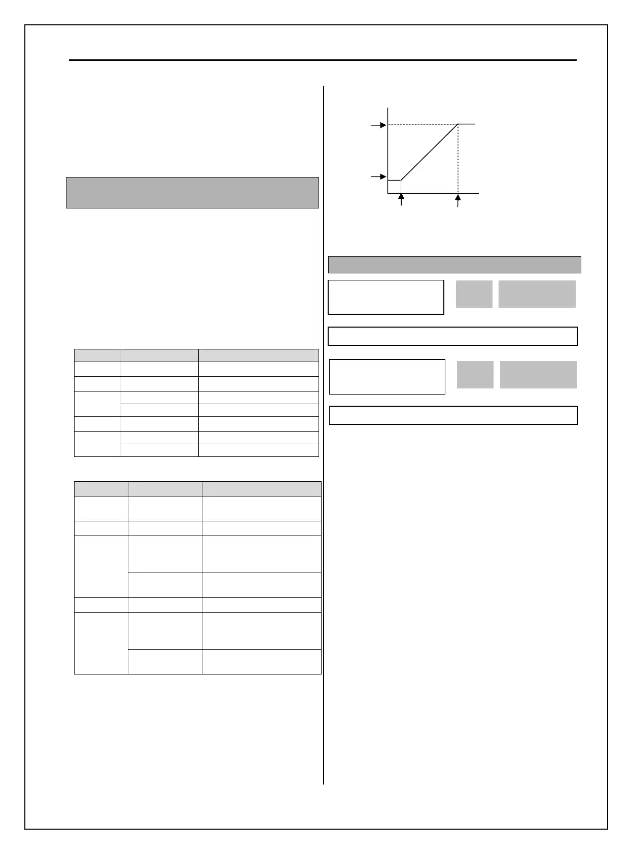
Terminal I (0 ~ 20 mA)
Set freq (target value)
I/O-07
I Minimum
current
I/O-08
I/O-10
I/O-09
I Maximum
current