Chapter 6 - Parameter Description [DRV]
6-4
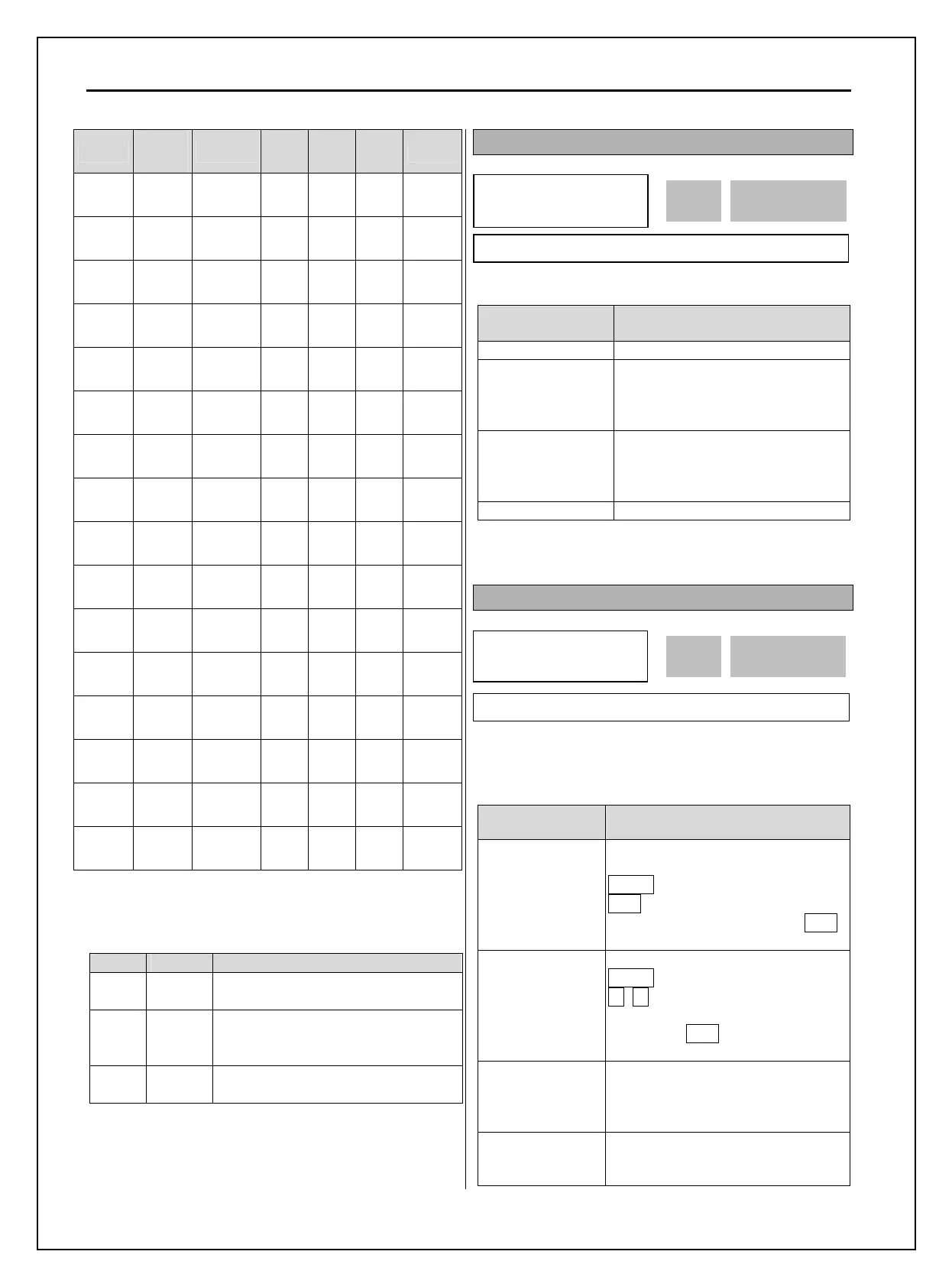
Code
LCD
display
Name
XCEL
-H
XCEL
-M
XCEL
-L
Default
DRV-01 Acc time
Acc time
0
0 0 0 20 sec
DRV-02 Dec time
Dec time
0
0 0 0 30 sec
I/O-50 ACC-1
Acc time
1
0 0 1 20 sec
I/O-51 DEC-1
Dec time
1
0 0 1 20 sec
I/O-52 ACC-2
Acc time
2
0 1 0 30 sec
I/O-53 DEC-2
Dec time
2
0 1 0 30 sec
I/O-54 ACC-3
Acc time
3
0 1 1 40 sec
I/O-55 DEC-3
Dec time
3
0 1 1 40 sec
I/O-56 ACC-4
Acc time
4
1 0 0 50 sec
I/O-57 DEC-4
Dec time
4
1 0 0 50 sec
I/O-58 ACC-5
Acc time
5
1 0 1 40 sec
I/O-59 DEC-5
Dec time
5
1 0 1 40 sec
I/O-60 ACC-6
Acc time
6
1 1 0 30 sec
I/O-61 DEC-6
Dec time
6
1 1 0 30 sec
I/O-62 ACC-7
Acc time
7
1 1 1 20 sec
I/O-63 DEC-7
Dec time
7
1 1 1 20 sec
FU2-74 [Accel/Decel time scale]
Set the Accel/Decel time unit.
* Up to 6000 sec settable via LE-200 keypad.
Setting Unit Description
0 0.01 sec
Minimum 0 sec settable
Maximum 60 sec settable
1 0.1 sec
Minimum 0 sec settable
Maximum 600 sec settable
(Factory setting)
2 1 sec
Minimum 0 sec settable
Maximum 6000 sec settable*
DRV-03: Drive Mode (Run/Stop Method)
Select the source of run/stop command.
Setting Range Description
Keypad Run/Stop control by Keypad.
Fx/Rx-1
Run/Stop control by Control
Terminals FX, RX. (Method 1)
FX: Forward Run/Stop
RX: Reverse Run/Stop
Fx/Rx-2
Run/Stop control by Control
Terminals FX, RX. (Method 2)
FX: Run/Stop command
RX: Forward/Reverse selection
Int. 485 Run/Stop control by RS485.
DRV-04: Frequency Mode
If the DRV-04 [Frequency Mode] is set to V1, V1S, I,
V1+I, see the description of I/O-01~16 [Analog
Voltage/Current input signal adjustment].
Setting Range Description
Keypad-1
Frequency is set at DRV-00. The
frequency is changed by pressing
PROG key and entered by pressing
ENT key. The inverter does not output
the changed frequency until the ENT
key is pressed.
Keypad-2
Frequency is set at DRV-00. Press
PROG key and then by pressing the
▲, ▼ key, the inverter immediately
outputs the changed frequency.
Pressing the
ENT key saves the
changed frequency.
V1
Apply the frequency reference (0-12V)
to the “V1” control terminal. Refer to
the I/O-01 to I/O-05 for scaling the
signal.
V1S
Apply the frequency reference
-12~12V to terminal V1. Refer to the
I/O-01 to I/O-05
DRV
►
Drive mode
03
Fx/Rx-1
1 03
Factory Default: Fx/Rx-1 1
DRV► Freq mode
04 Keypad-1
0 04
Factory Default: Keypad-1 0