Chapter 6 - Parameter Description [I/O]
6-47
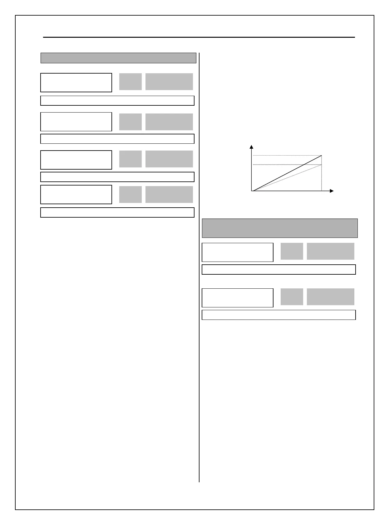
I/O-70~73: S0, S1 terminal select
Analog meter displays the inverter output Frequency,
Current, Voltage, DC link voltage and External PID
output with pulse signals on the S0, S1 terminal. The
average output voltage range is 0V to 10V. I/O-71,
73 are used to adjust the S0, S1 output gain value.
[Frequency]
S0/S1 terminal outputs inverter output frequency.
The output value is determined by,
S0/S1 Output Voltage = (Output freq. / Max. freq.) ×
10V ×(IO-71 or 73)/ 100
[Current]
S0/S1 terminal outputs inverter output current. The
output value is determined by,
S0/S1 Output Voltage = (Output current / Rated
current) × 10V × (IO-71 or 73)/ 100
[Voltage]
S0/S1 terminal outputs inverter output voltage. The
output value is determined by,
S0/S1 Output Voltage = (Output voltage / Max.
output voltage) × 10V × (IO-71 or 73)/ 100
[DC link vtg]
S0/S1 terminal outputs the DC link voltage of
inverter. The output value is determined by,
S0/S1 Output Voltage = (DC link voltage/Max. DC
link voltage) × 10V × (IO-71 or 73)/100
[Ext.PID Out]
S0/S1 terminal outputs External PID output. The
output value is determined by,
S0/S1 output voltage= (External PID output/10000) *
10V * S0,S1 output gain(I/O-71,73) / 100
Note: Maximum DC Link Voltage for 200V class
is 410V and for 400V class 820V.
I/O-74: FDT (Frequency Detection) Level
I/O-75: FDT Bandwidth
These functions are used in I/O-76-79
[Programmable Digital Auxiliary Output Terminal].
See [FDT-#] in I/O-76~79.
Use Sub-Boards if you need to use Programmable
Digital output terminal Q1, Q2, and Q3.
I/O►
S0 mode
70 Frequency
0 70
Factory Default: Frequency 0
I/O►
S0 adjust
71 100 %
100
71
Factory Default: 100 % 100
I/O►
FDT freq
74 30.00 Hz
30.00 74
Factory Default: 30.00 Hz 30.00
I/O►
FDT band
75 10.00 Hz
10.00 75
Factory Default: 10.00 Hz 10.00
I/O►
S1 mode
72 Frequency
0 72
Factory Default: Frequency 0
I/O►
S1 adjust
73 100 %
100 73
Factory Default: 100 % 100
S0/S1 -5G
10 V
Gain*10 V
Output V