Chapter 3 - Installation
3-10
3.2.2 Wiring power terminals
◈ Wiring Precautions
1) The internal circuits of the inverter will be damaged if the incoming power is connected and applied to
output terminals (U, V, W).
2) Use ring terminals with insulated caps when wiring the input power and motor wiring.
3) Do not leave wire fragments inside the inverter. Wire fragments can cause faults, breakdowns, and
malfunctions.
4) For input and output, use wires with sufficient size to ensure voltage drop of less than 2%.
5) Motor torque may drop of operating at low frequencies and a long wire run between inverter and motor.
6) The cable length between inverter and motor should be less than 150m (492ft). Due to increased leakage
capacitance between cables, overcurrent protective feature may operate or equipment connected to the
output side may malfunction. (But for products of less than 30kW, the cable length should be less than 50m
(164ft).)
7) The main circuit of the inverter contains high frequency noise, and can hinder communication
equipment near the inverter. To reduce noise, install line noise filters on the input side of the inverter.
8) Do not use power factor capacitor, surge killers, or RFI filters on the output side of the inverter. Doing
so may damage these components.
9) Always check whether the LCD and the charge lamp for the power terminal are OFF before wiring
terminals. The charge capacitor may hold high-voltage even after the power is disconnected. Use caution to
prevent the possibility of personal injury.
◈ Grounding
1) The inverter is a high switching device, and leakage current may flow. Ground the inverter to avoid
electrical shock. Use caution to prevent the possibility of personal injury. The ground impedance for 200V
class is 100 ohm with 400V class 10ohm.
2) Connect only to the dedicated ground terminal of the inverter. Do not use the case or the chassis screw
for grounding.
3) The protective earth conductor must be the first one in being connected and the last one in being
disconnected.
4) As a minimum, grounding wire should meet the specifications listed below. Grounding wire should be
as short as possible and should be connected to the ground point as near as possible to the inverter.
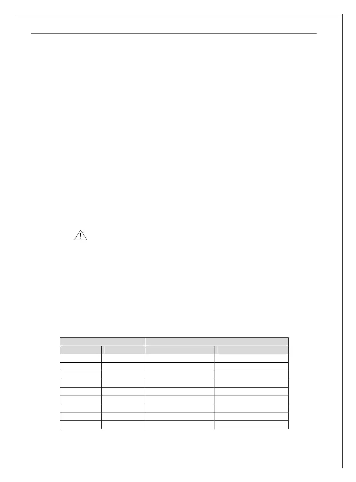
Inverter Capacity Grounding wire Sizes, AWG or kcmil (mm²)
kW HP 200V Class 400V Class
5.5 ~ 7.5 7.5 ~ 10 10 (5.5) 12 (3.5)
11 ~ 15 15 ~ 20 6 (14) 8 (8)
18.5 ~ 30 25 ~ 40 4 (22) 6 (14)
37 ~ 55 50 ~ 75 - 4 (22)
75 ~ 90 100 ~ 125 - 2 (38)
110 ~132 150 ~ 200 - 1/0 (60)
160 ~ 280 250 ~ 350 - 4/0 (100)
315 ~ 375 400 ~ 600 - 300 (150)
450 700 - 400 (200)