Chapter 6 - Parameter Description [APP]
6-56
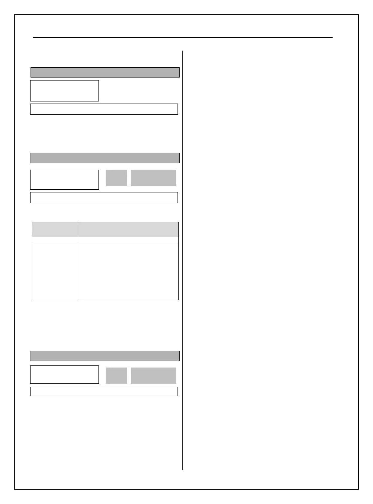
6.5 Application group [APP]
APP-00: Jump to desired code #
Jumping directly to any parameter code can be
accomplished by entering the desired code number.
This code is available only with LCD keypad.
APP-01: Application Mode Selection
This code sets the application mode.
Setting Range Description
None Application mode is not selected.
MMC
MMC (Multi-Motor Control) mode is
selected in application group. Related
parameters (APP-40~71) are displayed.
I/O-76~79 [Programmable digital
Aux. relay output] is automatically set to
“MMC.” If less than 4 aux motors are
connected, the remainder relays can be
used for other functions.
☞ Caution: I/O-76~79 value is not initialized
automatically even though “None” is set after
setting “MMC”. In this case, set the I/O-76~79
again for desired selection.
APP-02: PID Operation Selection
This function can be used for Process control like
flow, pressure, and air volume control.
To use this function, set APP-02 [proc PI mode] to
“Yes”. PID control detects the amount of feedback
from a sensor and compares it with the target value.
If the values differ, this function produces an output
to eliminate the deviation. In other words, this control
matches the feedback amount with the target value.
For HVAC or Pump applications, the PID control can
be used to adjust the actual output by comparing a
feedback with a ‘Set-point’ given to the inverter. This
‘Set-point’ can be in the form of Speed, Temperature,
Pressure, Flow level, etc. The ‘Set-point’ and the
feedback signals are provided externally to the
inverter analog input terminals. The inverter
compares the signals in calculating ‘total-error’
which is reflected in the inverter output.
Note: PID control can be bypassed to manual operation
temporarily by defining one of the multifunction
input terminals (M1~M8, P4~P6) to “Open-loop”.
The inverter will change to manual operation from
PID control when this terminal is ON, and change
back to PID control when this terminal is OFF.
[P Control] This is to compensate the error for a
system input proportionally. This is used to make the
controller to respond fast for an error. When P
control is used alone, the system is easily affected by
an external disturbance during steady state.
[I Control] This is to compensate the error of a
system integrally. This is used to compensate the
steady state error by accumulating them. Using this
control alone makes the system unstable.
[PI control] This control is stable in many systems.
If “D control” is added, it becomes the 3
rd
order
system. In some systems this may lead to system
instability.
[D Control] Since the D control uses the variation
ratio of error, it has the merit of controlling the error
before the error is too large. The D control requires a
large control quantity at start, but has the tendency of
increasing the stability of the system. This control
does not affect the steady state error directly, but
increases the system gain because it has an
attenuation effect on the system. As a result, the
differential control component has an effect on
decreasing the steady state error. Since the D control
operates on the error signal, it cannot be used alone.
Always use it with the P control or PI control.
APP
► Proc PI mode
02 No
0 02
Factory Default: No 0
APP►
Jump code
00 1
Factory Default: 1
APP►
App. mode
01 None
0 01
Factory Default: None 0