Chapter 6 - Parameter Description [I/O]
6-44
I/O-50~63: 1
st
~7
th
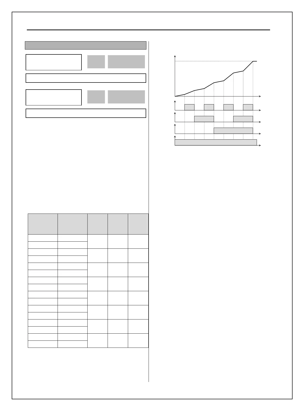
Accel/Decel Time
[XCEL-L, XCEL-M, XCEL-H]
By setting M1, M2 and M3 terminals to ‘XCEL-L’,
‘XCEL-M’ and ‘XCEL-H’ respectively, up to 8
different Accel and Decel times can be used. The
Accel/Decel time is set in DRV-01 ~ DRV-02 and
I/O-50 ~ I/O-63.
The Accel/Decel time is determined by the
combination of M1, M2 and M3 terminals as shown
in the following table.
Parameter
Code
Accel/Decel
Time
XCEL-
H
(M3)
XCEL-
M
(M2)
XCEL-
L
(M1)
DRV-01 Accel Time-0
DRV-02 Decel Time-0
0 0 0
I/O-50 Accel Time-1
I/O-51 Decel Time-1
0 0 1
I/O-52 Accel Time-2
I/O-53 Decel Time-2
0 1 0
I/O-54 Accel Time-3
I/O-55 Decel Time-3
0 1 1
I/O-56 Accel Time-4
I/O-57 Decel Time-4
1 0 0
I/O-58 Accel Time-5
I/O-59 Decel Time-5
1 0 1
I/O-60 Accel Time-6
I/O-61 Decel Time-6
1 1 0
I/O-62 Accel Time-7
I/O-63 Decel Time-7
1 1 1
0: OFF, 1: ON
[Multi-Accel/Decel Time Operation]
[Dc-brake]
DC Injection Braking can be activated during inverter
stop by configuring one of the Programmable digital
input terminals (M1-M8) to ‘Dc-bake’. The preset
DC-start value in FU1-22 is applied. To activate the
DC Injection Braking, close the contact of the
assigned terminal while the inverter is stopped.
[2
nd
function]
See APP 20~29 for details.
[Exchange]
Exchange is used to bypass the motor from the
inverter line to commercial power or the opposite. To
bypass the motor to commercial line, set the
‘Exchange’ function in one of the Programmable
digital input terminal in I/O-20~27 and ‘INV line’,
‘COMM line’ function in Programmable digital
output terminal(AX-CX) in I/O-76~79.
Speed search function (FU2-22) is activated
automatically during exchanging operation,
enabling smooth exchange.
The following 3 setting should be made to activate
this function;
1) Set one of the Programmable digital input
terminal (I/O-20~27) to 8 “Exchange.”
2) Set one of the Programmable digital (Aux.
Contact) Output terminal to 16 “INV line.”
3) Set one of the Programmable digital (Aux.
Contact) Output terminal to 17 “COMM line.”
M1
ON
Output Frequency
Time
Time
M2
ON
Time
M3
ON
Time
FX
ON
Time
ON ON ON
ON
Ref.
Fre
.
Time
Time
Time
Time
Time
Time
Time
Time
I/O
►
Acc time-1
50 20.0 sec
20.0 50
Factory Default: 20.0 sec 20.0
I/O
►
Dec time-1
51 20.0 sec
20.0 51
Factory Default: 20.0 sec 20.0

 Loading...


