Chapter 6 - Parameter Description [I/O]
6-43
Code
Step speed
Frequency
Spd-
X
Spd-
H
Spd-
M
Spd-
L
JO
G
DRV-
00
S. Freq-0
(Zero Spd)
0 0 0 0 0
I/O-30 Jog Freq X X X X X
DRV-
05
S. Freq-1
(Spd 1)
0 0 0 1 0
DRV-
06
S. Freq-2
(Spd 2)
0 0 1 0 0
DRV-
07
S. Freq-3
(Spd-3)
0 0 1 1 0
I/O-31 S. Freq-4
(Spd-4)
0 1 0 0 0
I/O-32 S. Freq-5
(Spd-5)
0 1 0 1 0
I/O-33 S. Freq-6
(Spd-6)
0 1 1 0 0
I/O-34 S. Freq-7
(Spd-7)
0 1 1 1 0
I/O-35 S. Freq-8
(Spd-8)
1 0 0 0 0
I/O-36 S. Freq-9
(Spd-9)
1 0 0 1 0
I/O-37 S. Freq-10
(Spd-10)
1 0 1 0 0
I/O-38 S. Freq-11
(Spd-11)
1 0 1 1 0
I/O-39 S. Freq-12
(Spd-12)
1 1 0 0 0
I/O-40 S. Freq-13
(Spd-13)
1 1 0 1 0
I/O-41 S. Freq-14
(Spd-14)
1 1 1 0 0
I/O-42 S. Freq-15
(Spd-15)
1 1 1 1 0
0: OFF, 1: ON, X: Ignored (Jog first)
Speed-L: Lowest bit in Multi-Step speed input
Speed-M: Middle bit in Multi-Step speed input
Speed-H: High bit in Multi-Step speed input
Speed-X: Highest bit in Multi-Step speed input
Note 1: ‘Speed 0’ is set in DRV-04.
Note 2: If the ‘Jog’ terminal is ON, inverter operates at Jog
frequency regardless of other terminal inputs
.
DRV-04 Data DRV-00 Speed 0 Freq source
Keypad-1 Digital Freq Ref Keypad
Keypad-2 Digital Freq Ref Keypad
V1 Analog Freq Ref. Terminal
V1S Analog Freq Ref. Terminal
I Analog Freq Ref. Terminal
V1+I Analog Freq Ref. Terminal
Pulse Pulse Freq Ref. Terminal
Int. 485 Communication Terminal
Ext. PID Ext. PID Freq Ref. Keypad or
Terminal
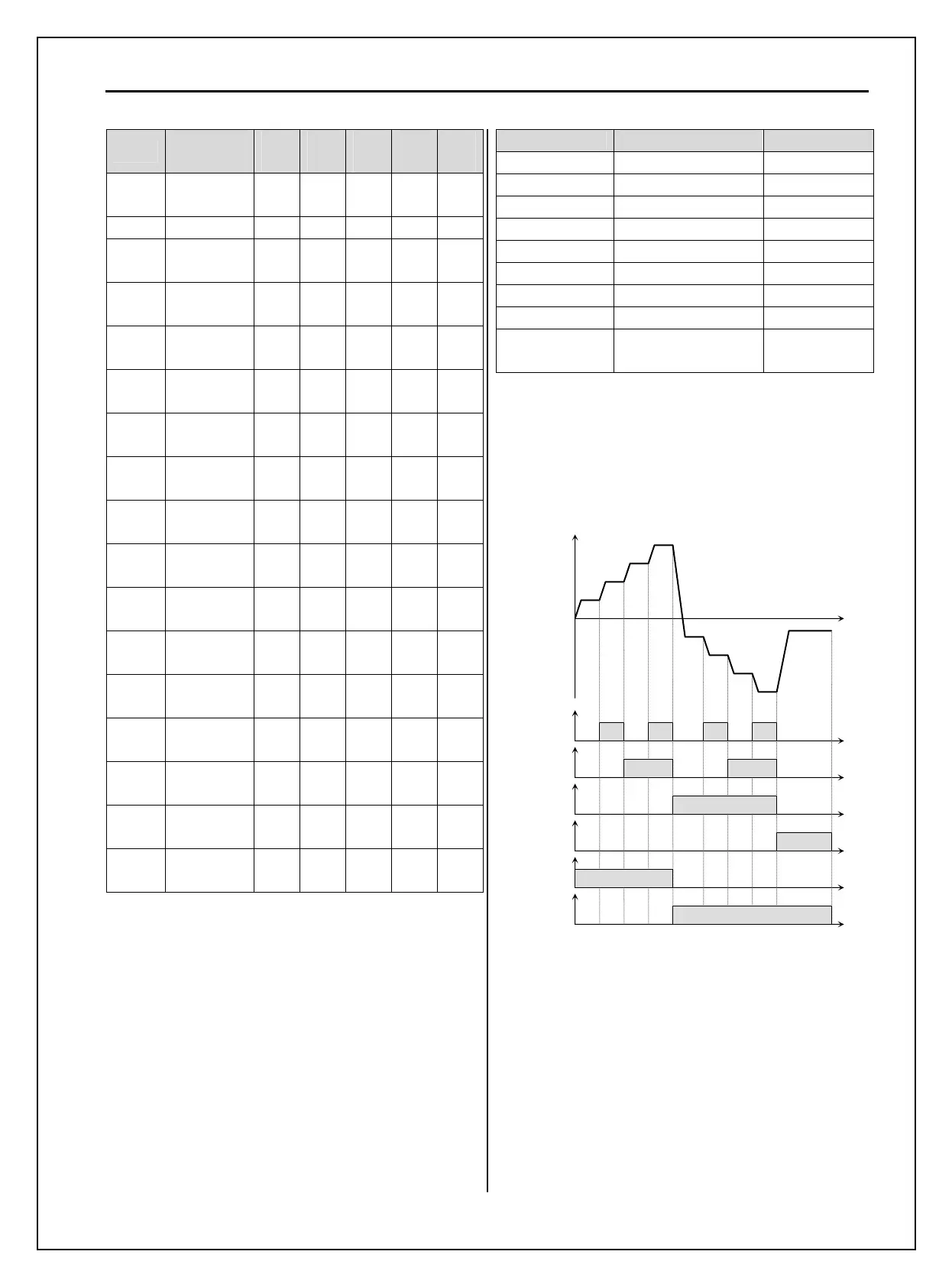
♣ Setting example
M1=Speed-L, M2=Speed-M, M3=Speed-H, M4=Jog
M5=BX, M7=FX, M8=RX
Step speed is to be set in DRV-05~06, I/O-31~42
[Multi-Step Frequency Operation]
Speed-L
ON ON
Speed-M
ON ON
S
ee
-H
ON
JOG
ON
FX
ON
RX
ON
ON ON
Step
0
Step
1
Step
2
Step
3
Step
4
Step
5
Step
6
Step
7
Jog

 Loading...


