Chapter 6 - Parameter Description [I/O]
6-46
[Main-drive]
When an option board or embeded RS485
communication is used for the frequency setting and
the run/stop command setting, and the setting is ON,
the inverter operation can be changed to Option (or
RS485) operation without changing parameters.
The set values in DRV-92 [Frequency Mode 2] and
DRV-91 [Drive Mode 2] are applied to the Option (or
RS485) operation.
Note: To switch to RS485 communication operation
during Main-drive operation, Stop the inverter
first and disable Main-drive and connect RS485
communication.
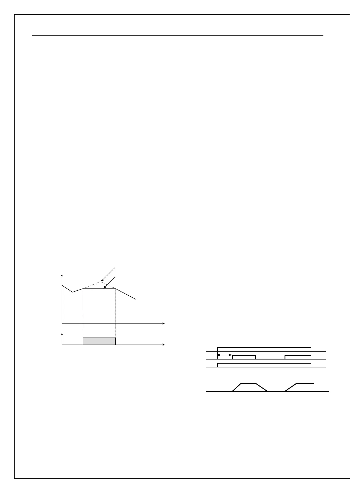
[Analog hold]
When there is an analog input signal for frequency
reference and ‘Analog hold’ terminal is ON, inverter
fixes its output frequency regardless of the frequency
reference. When the terminal is OFF, the actual
frequency reference will be applied.
This function is useful when a system requires
constant speed after acceleration or freq reference is
not necessary to be changed.
[Analog hold Operation]
[XCEL stop]
Inverter stops accelerating and decelerating when this
terminal is ON.
[P Gain 2]
This function is used to change P-Gain during PID
operation. When this terminal is ON, PID controller
changes P-Gain to PID P2-Gain.
Refer to PID Control Block Diagram.
[Interlock 1, 2, 3, 4]
This function is used for MMC operation. When
MMC is selected in APP-01 and interlock is set, M1,
M2, M3 and M4 are automatically assigned for
Interlock function. Therefore, these terminals cannot
be used for setting other functions when interlock is
active. Use M5, M6, M7, and M8 for other function
setting. Refer to MMC operation.
[Reset]
This function is set to use it as fault reset terminal
when ON.
[BX]
This function is set to use it as Emergency Stop
terminal when ON.
[JOG]
This function is set to use Jog operation terminal
when ON.
[FX/RX]
This function is set to issue Forward/Reverse Run.
[Ana Change]
Inverter changes its frequency reference source from
V1 to I when ON.
Ex) In the case of V1+I operation, V1 is the
default setting and it is changed to I operation
when the terminal is turned ON.
[Pre excite]
This setting switches the inverter to pre-excition state.
This function applies the DC magnetizing current to a
motor to build the flux in Sensorless control. When
the operation command is set to ON, the state
changes from pre-excitation to normal.
I/O
Run/Stop
Id
We
A: Pre-excitating
[Ext.PID Run]
External PID controller begins operation when the
defined terminal is turned ON. This can be operated
regardless of inverter reference command or used in
conjunction with internal PID operation.
Refer to
External PID operation for details.
A
M1-CM
‘Analog hold’
Analog frequency
reference
Time
ON
Time
Reference Frequency
Output Frequency

 Loading...


