iii
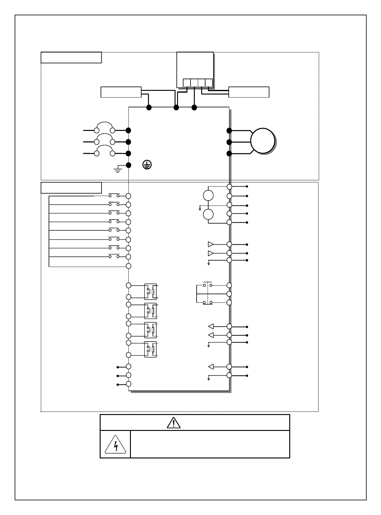
6. BASIC WIRING
AC Input
50/60 Hz
U
V
W
G
R(L1)
S(L2)
T(L3)
N(-)
DB Unit(Optional)
DB Resistor
φ
3
MCCB(Option)
M1
M2
M3
M4
M6
M8
M7
MOTOR
Programmable Digital Input 1(Speed L)
Programmable Digital Input 2(Speed M)
Programmable Digital Input 3(Speed H)
Fault Reset (RST)
Jog Frequency Reference (JOG)
Forward Run command (FX)
Reverse Run command (RX)
Common Terminal
Fault Contact Ouput
less than AC250V (DC30V), 1A
P2(+)P1(+)
DC Bus Choke (Optional )
Dynamic
Braking Unit
(Optional)
P
N
B1
B2
DC Bus Choke DB Resistor
M5
Inverter Disable (BX)
V+
V1
5G
V-
I
Analog Power Source (+12V)
+
-
+
-
Analog Power Source (-12V)
Frequency reference (0~20mA or 4~20mA)
Frequency reference (0~12V,V1S : -12~12V)
Frequency reference common terminal
S1
S0
5G
Output Frequency Meter
Output Voltage Meter
Common for output meter signal
3A
3C
3B
5G
B0
A0
Frequency Reference (Pulse : 0 ~ 100kHz)
Common for Frequency Reference (Pulse)
5G
NT
External motor thermal detection
A1
C1
A2
C2
A3
C3
A4
C4
C-
C+
CM
RS485 Signal
RS485 Common
CM
Note : 1) 5G is Common Ground for Analog Input/Output.
2) Use terminal V1 for V1, V1S (0~12V, -12 ~ 12V) input.
Programmable Digital Output
CAUTION
■ Risk of Electric Shock
More than one disconnect switch may be required
to de-energize the equipment before servicing.
Control Circuit
Main Power Circuit