SET-UP AND INSTALLATION MLC650 OPERATOR MANUAL
4-10
Published 08-12-19, Control # 224-13_v2
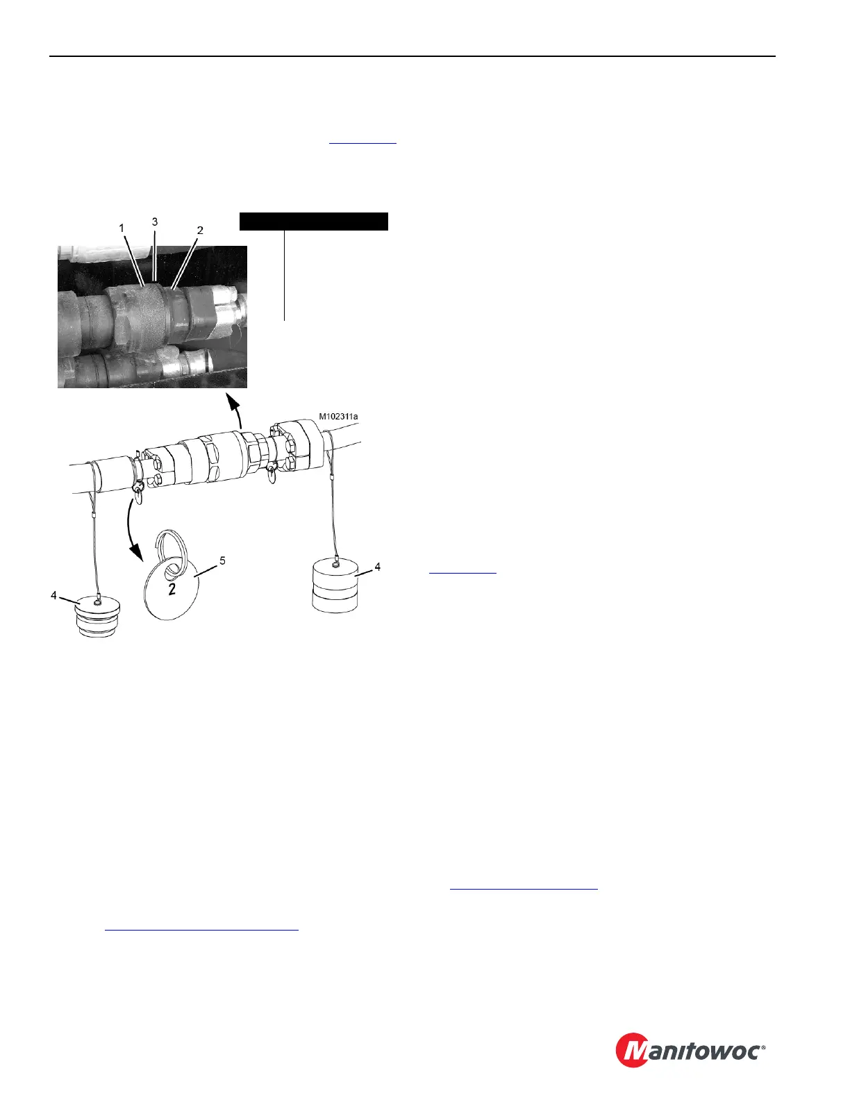
HYDRAULIC HOSE IDENTIFICATION
Where necessary, the hydraulic hoses and corresponding
couplers have identification tags (5) as shown in Figure 4-10
.
Match the number on the hose with the number on the decal
or the corresponding coupler to ensure proper connection.
CONNECTING/DISCONNECTING
HYDRAULIC HOSES AND ELECTRIC
CABLES
Always STOP ENGINE before performing the following steps
during crane assembly and disassembly:
• Connecting and disconnecting hydraulic lines. It will be
easier to connect and disconnect the couplers when
there is no pressure in the system.
• Connecting and disconnecting electric cables. The
potential for damage to the electric components exists if
the engine is not stopped.
NOTE: To stop the engine if it was started from the remote
control, turn the external engine switch (6,
Figure 4-12 on page 4-12
) COUNTER-
CLOCKWISE to the STOP position.
To stop the engine if it was started from the cab,
use the ignition switch in the cab.
HOSE AND CABLE CLEANLINESS
To prevent dirt from entering the hydraulic systems or from
damaging the electrical connectors:
• Thoroughly clean hydraulic fittings and electric
connectors before connecting them.
• Thoroughly clean protective caps before attaching them
to hoses, tubes, or cables.
• Do not drag hydraulic hose fittings or hoses and
electrical connectors or cables on the ground.
NOTE: Apply a light coat of silicone lubricant to the threads
of all protective caps, couplers, and connectors to
help in preventing the threads from seizing.
PIN AND CONNECTING HOLE
CLEANLINESS
To prevent dirt from damaging closely machined surfaces of
pins and connecting holes, perform the following tasks each
time the pins are installed:
• Thoroughly clean all pins and connecting holes.
• Apply a light coat of grease to all pins, contacting
surfaces, and connecting holes.
TIGHTENING HYDRAULIC COUPLERS
Connect each screw-to-connect coupler and nipple
(Figure 4-10
), as follows:
1. Lubricate coupler internal threads (1), nipple threads (2),
and nipple O-ring (3) with LPS-2 Aerosol Lubricant.
2. Hand tighten the coupler on the nipple.
3. Using opened-end wrenches from the parts box, tighten
the coupler until there is metal-to-metal contact between
the coupler and the nipple. Nipple o-ring must not be
visible.
To avoid damage, do not exceed a torque of:
• Size -06 = 2,2 Nm (1.62 lbf ft)
• Size -08 = 1,8 Nm (1.33 lbf ft)
• Size -12 = 5,6 Nm (4.13 lbf ft)
• Size -20 = 8,2 Nm (6.04 lbf ft)
• Size -24 = 26,0 Nm (19.16 lbf ft)
4. Check that the hydraulic tank shut-off valve (see
Figure 4-16 on page 4-17
) is open.
5. Check for leaks after the crane has been operated with
the hydraulic oil at operating temperature. Retighten the
couplers if necessary.
Item Description
1 Coupler
2Nipple
3 O-ring (not visible)
4Dust Cap
5 Identification Tag
FIGURE 4-10