Manitowoc Published 08-12-19, Control # 224-13_v2 4-117
MLC650 OPERATOR MANUAL SET-UP AND INSTALLATION
Prepare 4M Insert
See Figure 4-87, for the following steps:
NOTE: To lift inserts, use shackles and lifting slings
attached to the self-erect cylinder rod end.
Reference charts found in Figure 4-7 on page 4-6
.
1. Position the trailer carrying the 4M insert on the desired
side of the crane at the specified radius.
2. Attach four nylon lifting slings to the four lifting lugs on
the 4M insert.
3. Lift the 4M insert from the trailer and remove the trailer.
4. Align the 4M insert with the boom butt for installation.
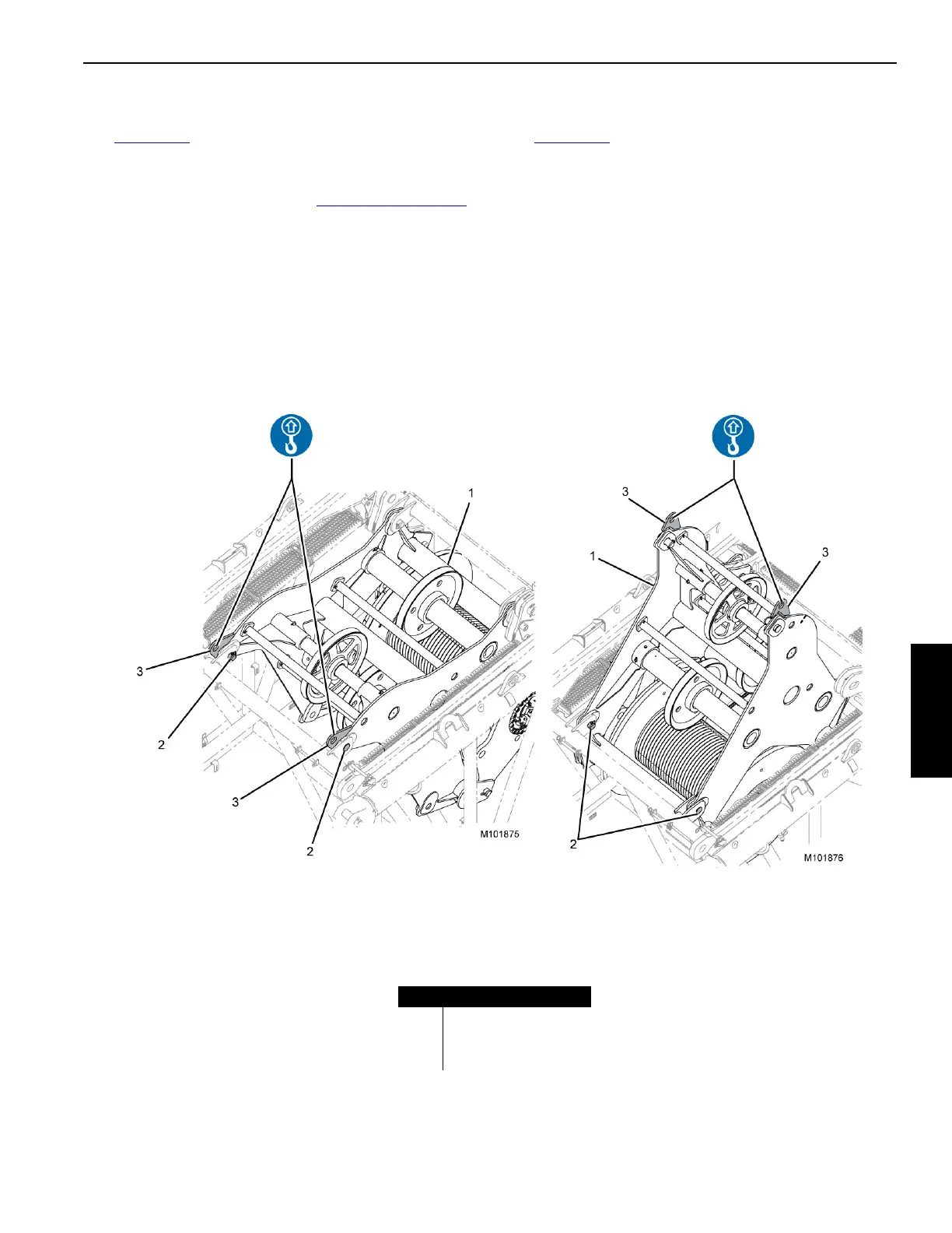
Raise Wire Rope
See Figure 4-88, for the following steps:
1. Connect two nylon slings to the wire rope guide lifting
lugs (3) using shackles and raise until slack is removed
from slings.
2. Remove safety pins and pins (2).
3. Raise the wire rope assembly until the holes align in the
working position.
4. Install the pins and safety pins.
5. Lower self-erect cylinder to create slack in the slings,
remove shackles and slings.
Item Description
1 Wire Rope Guide
2 Pins and Safety Pins
3 Lifting Lugs
FIGURE 4-88
Stored Position
Working Position
(2)
(2)