Manitowoc Published 08-12-19, Control # 224-13_v2 4-107
MLC650 OPERATOR MANUAL SET-UP AND INSTALLATION
Install/Remove Lower Boom Point
See Figure 4-82 for the following procedures.
Install Lower Boom Point
Disregard this procedure if the lower boom points are already
attached to the boom top in the working position.
1. Remove the connecting pins (2, View F or G) from the
desired lower boom point.
2. Using shackles, rig two lifting slings from an assist crane
to the lifting lugs (9, View F) or to the lifting links (10,
View G) on the lower boom point.
3. Lift the lower boom point into position at the end of the
boom top and install the connecting pins (2, View A, B,
or C) with safety pins.
4. Lower the lower boom point until the lifting slings are
slack and disconnect the shackles and lifting slings.
5. Remove the pins (6 and 7, View D) and the links (8) from
the shipping position.
6. Install the links (slotted ends toward boom top) between
the lower boom points and the boom top using the
appropriate long and short pins as shown in View E.
Secure the pins and links with safety pins.
Removing Lower Boom Point
1. Remove the required pins (6 and 7, View E) and links (8)
from the working position.
2. Store the pins and links in the shipping position (View D).
3. Using shackles, rig two lifting slings from an assist crane
to the lifting lugs (9, View F) or to the lifting links (10,
View G) on the lower boom point being removed.
4. Lift the lower boom point until the lifting slings are in a
visual straight line drawn through the lower boom point’s
center of gravity (CG). Do not remove the connecting
pins (2) until this step is performed.
5. Remove the connecting pins (2, View A, B, or C) and lift
the lower boom point away from the boom top.
6. Store the connecting pins (2) in the lower boom point
holes.
WARNING
Crane Tipping Hazard!
To raise some boom and jib lengths, portions of the lower
boom point must be removed.
Refer to the appropriate Liftcrane Boom or Jib Capacity
Chart to determine lower boom point sheave
requirements and deducts.
WARNING
Crush Hazard!
The lower boom point can shift and crush your hand when
removing the connecting pins.
• Properly support the lower boom point as instructed
in the following procedure before removing the
connecting pins.
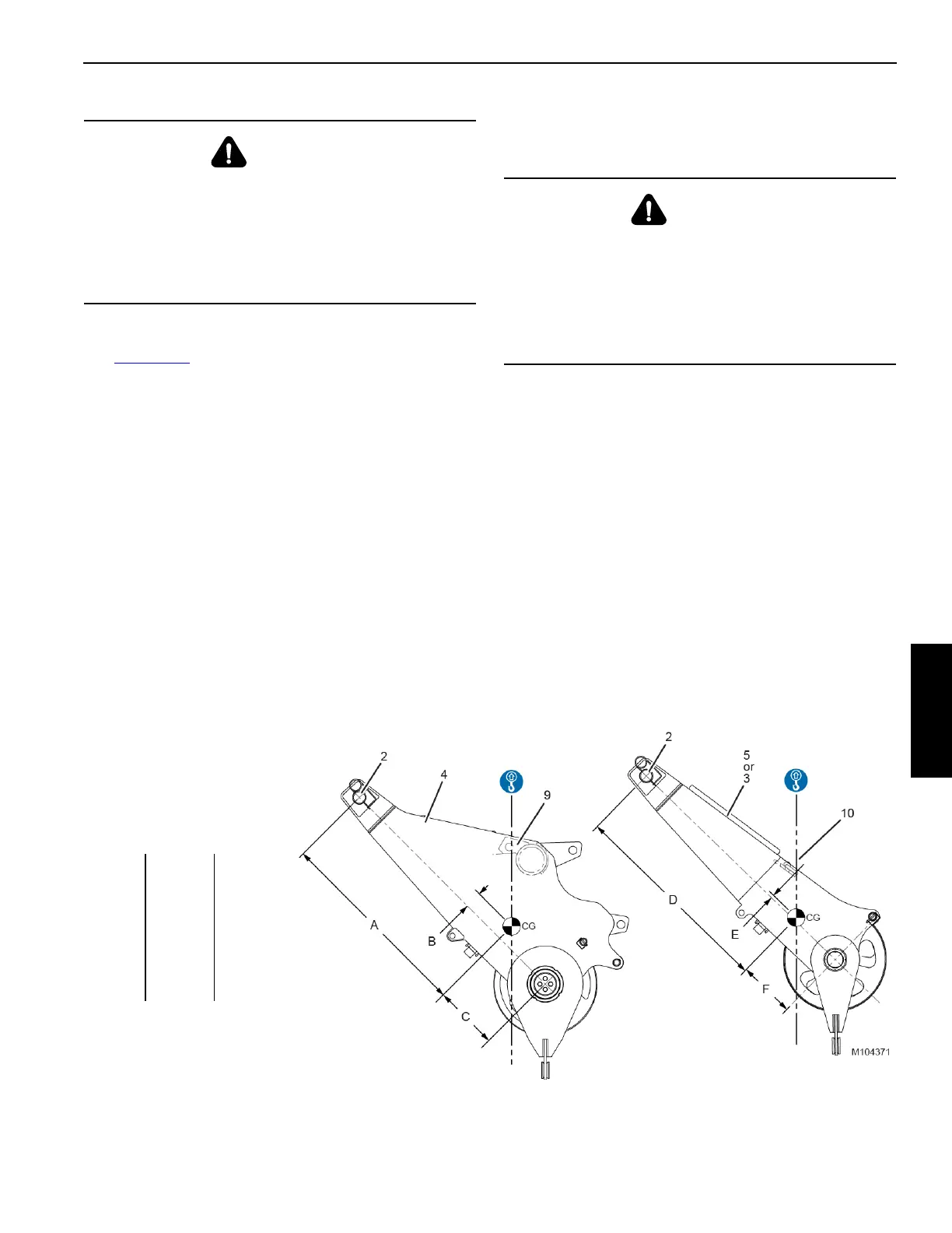
Item mm in
A 1 466,0 57.7
B 125,0 4.9
C 475,2 18.7
D 1 521,2 59.9
E23,0 0.9
F 420,0 16.5
FIGURE 4-82 continued
Lower Boom Point
Centers of Gravity
View F
View G
2 675 kg
5,897 lb
1 315 kg
2,899 lb