SET-UP AND INSTALLATION MLC650 OPERATOR MANUAL
4-174
Published 08-12-19, Control # 224-13_v2
Disconnecting Hydraulic Hoses
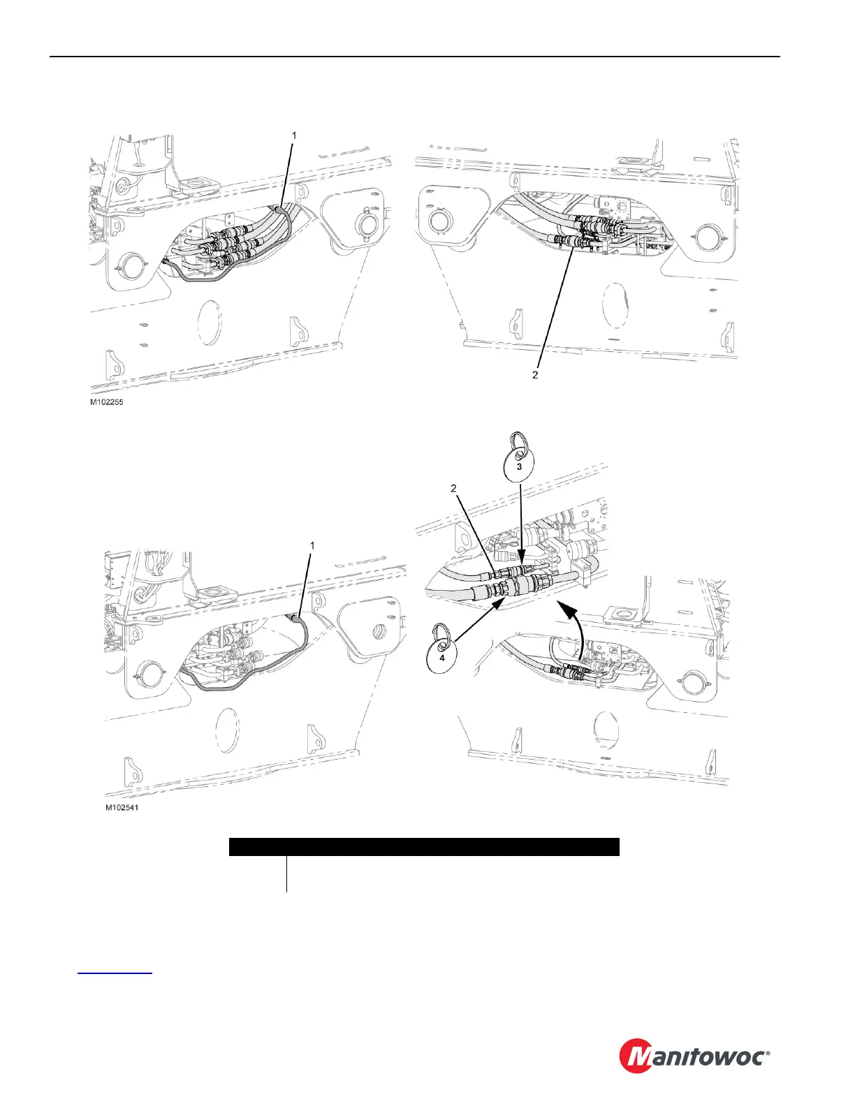
See Figure 4-134 for the following procedure:
1. Disconnect the adapter frame electrical cable (1).
2. On the right and left side of the crane, disconnect the
hydraulic hoses (2) and place them in the stored
position.
FIGURE 4-134
LEFT SIDE OF CRANE
RIGHT SIDE OF CRANE
WORKING POSITION
Item Description
1 Adapter Frame Electrical Cable (WFC1 connects to WRF2-J5)
2 Hydraulic Hose (qty 5)