Manitowoc Published 08-12-19, Control # 224-13_v2 4-211
MLC650 OPERATOR MANUAL SET-UP AND INSTALLATION
LOAD LINE REEVING
NOTE: The boom top can be reeved in various
configurations. See the reeving diagrams included
at the end of this section for each reeving option.
Guide Sheaves and Drums
See Figure 4-164 for identification of the load drums and the
guide sheaves.
Refer to the Reeving Diagrams at the end of this section for
rope routing over the boom top wire rope guide (7).
Once the wire rope is routed through the guide sheaves,
install all the rope guard pins, bars, and rollers to retain the
wire rope on the sheaves. Wire rope and sheaves can be
damaged if the rope is not properly retained on sheaves.
Load Block Identification
See the Boom Rigging Drawing at the end of this section for
a complete list of load blocks and hook and weight balls
available for use with this crane.
NOTE: Reference the block drawings included at the end
of this section for block assembly configurations.
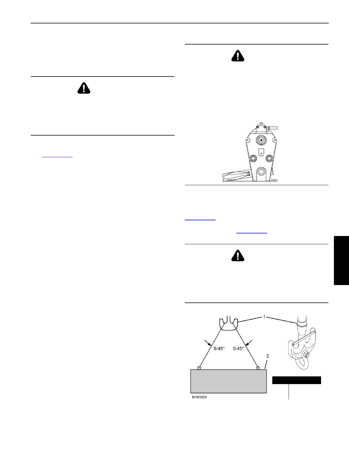
Duplex Hook
Attach the load (2) so it is balanced equally on the duplex
hook (1). The lifting slings must be within the angles given in
Figure 4-165
to achieve maximum hook capacity. The duplex
hook has a hole to which an optional shackle can be
attached as shown in Figure 4-165
.
WARNING
Falling Load Hazard!
Use only a load block or hook and weight ball with a
capacity equal to or greater than load to be handled.
The load block can fail if overloaded, allowing the load to
fall.
WARNING
Avoid Death or Serious Injury!
Exercise care when block is standing in vertical position,
as the potential for tipping exists. Potential causes of
tipping are unstable work area, boom movement and the
reeving process.
If work area is unstable, lay block flat on side plate.
WARNING
Falling Load Hazard!
Limit load to be handled with shackle to capacity of load
block or shackle, whichever is less.
Load block or shackle can fail if overloaded, allowing load
to fall.
FIGURE 4-165
Item Description
1 Duplex Hook
2 Load