Manitowoc Published 08-12-19, Control # 224-13_v2 4-125
MLC650 OPERATOR MANUAL SET-UP AND INSTALLATION
Connect Hydraulic Hoses from Crane to
Boom Butt
See Figure 4-95, for the following procedure:
1. Remove the hoses from the stored position on the crane
and the dust caps from the couplers.
2. Thoroughly clean all hydraulic connections.
3. Connect the hydraulic hoses from the crane to the
couplers on the boom butt. Match the identification tags
on the hoses to the identification tags on the couplers.
NOTE: The quantity of hydraulic hoses from the crane to
the boom butt will vary depending on your drum
options.
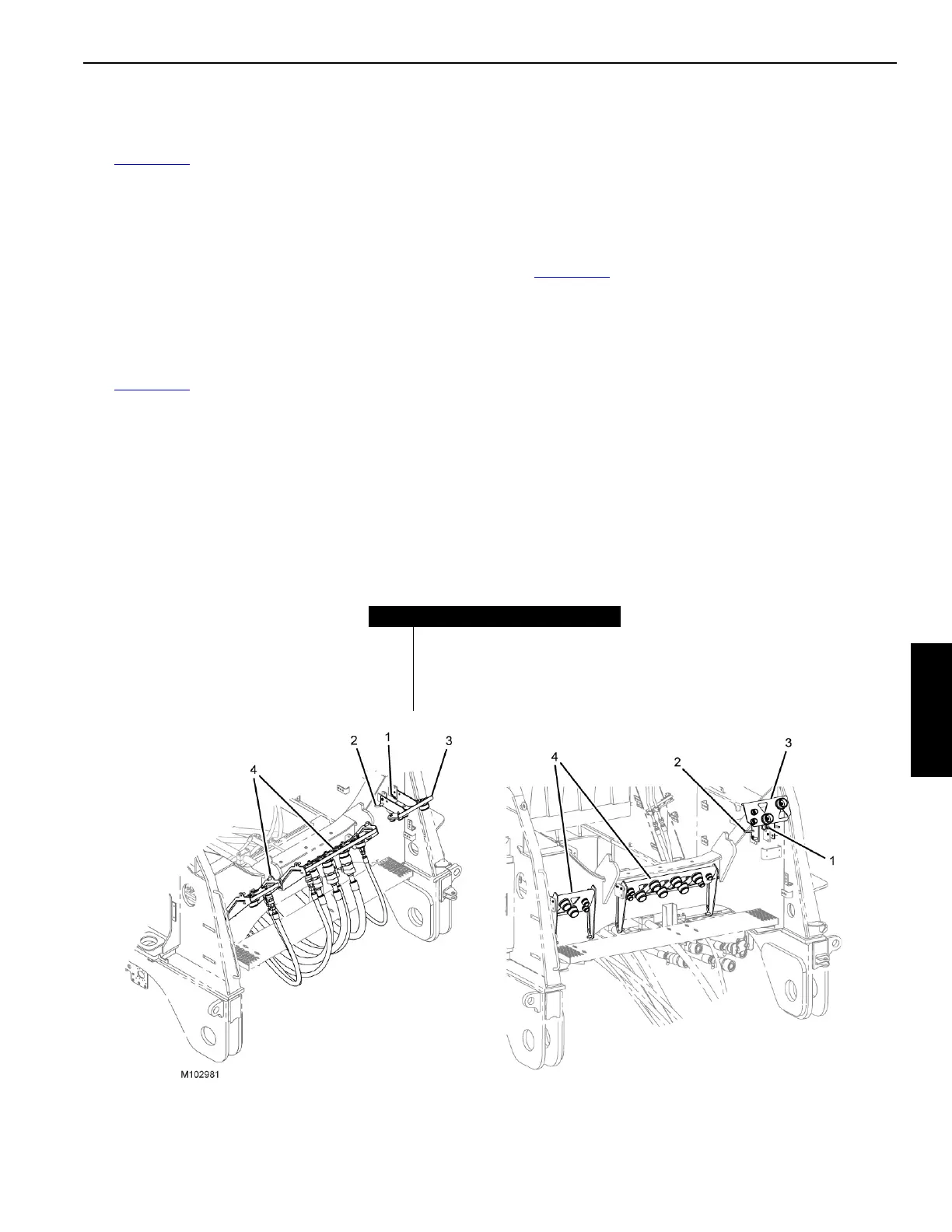
See Figure 4-96
, for the following procedure:
1. Remove the cotter (1) and hitch pins (2) from the hose
storage bracket (3).
2. Flip the hose storage bracket (3) up, align bracket holes,
and insert hitch (2) and cotter pins (1).
3. Remove the cotter (1) and hitch pins (2) from the hose
storage brackets (4).
4. Flip the hose storage brackets (4) up, slide them down,
align the hose storage bracket holes, and insert the hitch
(2) and cotter pins (1).
Connect Electric Cables from Boom Butt to
Crane
See Figure 4-95, for the following procedure:
1. Remove the dust caps from the electric cables and
receptacles.
2. Thoroughly clean all electric connections.
3. Disconnect the CAN terminator (4) from the end of
electric cable (3) and attach the dust cap to the
terminator.
4. Connect the electric cable (5) from the boom butt to the
receptacle on the crane.
5. Connect the electric cable (6) from the boom butt to the
receptacle on the crane.
FIGURE 4-96
Item Description
1Cotter Pins
2Hitch Pins
3 Hose Bracket
4 Hose Brackets
WORKING POSITION
STOWED POSITION