Manitowoc Published 08-12-19, Control # 224-13_v2 4-147
MLC650 OPERATOR MANUAL SET-UP AND INSTALLATION
Separating 4M Insert from Boom Butt
See Figure 4-113 for the following procedure:
1. Lower boom butt (11) and 4M insert (10) close to the
ground.
2. Remove the fixed pins (2, stored position) on the support
pedestal (1) on both sides of the boom butt. Lower the
boom butt support pedestals until the holes align, and
insert the fixed pins (2, working position).
3. Arrange blocking under the support pedestals and at the
end of the boom butt section as shown.
4. Lower the boom butt onto the blocking.
5. Remove the
SL 2 slings (3) from the boom butt and 4M
insert.
6. Attach the
SL 2 slings to the 4M insert (10).
7. Disconnect the electrical cables and securely fasten the
dust caps to all cable ends or receptacles. Store and
secure cables with plastic wire ties.
Be sure to install any CAN terminator plugs to avoid
electrical faults.
8. Disconnect the 4M hydraulic hoses (4b) from the boom
butt hydraulic line (5).
• Clean all hose couplers and dust caps.
• Securely fasten dust caps to all hydraulic couplers.
• Store the hydraulic hoses (4a).
9. Remove the safety pins (12) from the lower connecting
pins (13).
10. Either install the hand-held pin puller and remove both of
the lower connecting pins,
OR manually remove both lower connecting pins and
store them in the holders on the insert.
11. Lift the 4M insert. As the 4M insert rises, it will tilt toward
the boom butt, allowing the two sections to separate at
the bottom.
12. Continue to lift the 4M insert to allow the upper fixed pins
(14) to release from the upper hooked connector on the
boom butt.
13. Place the 4M insert on a trailer and disconnect the lifting
slings.
14. Secure the 4M insert to the trailer (see "Shipping Crane
Components" on page 4-137).
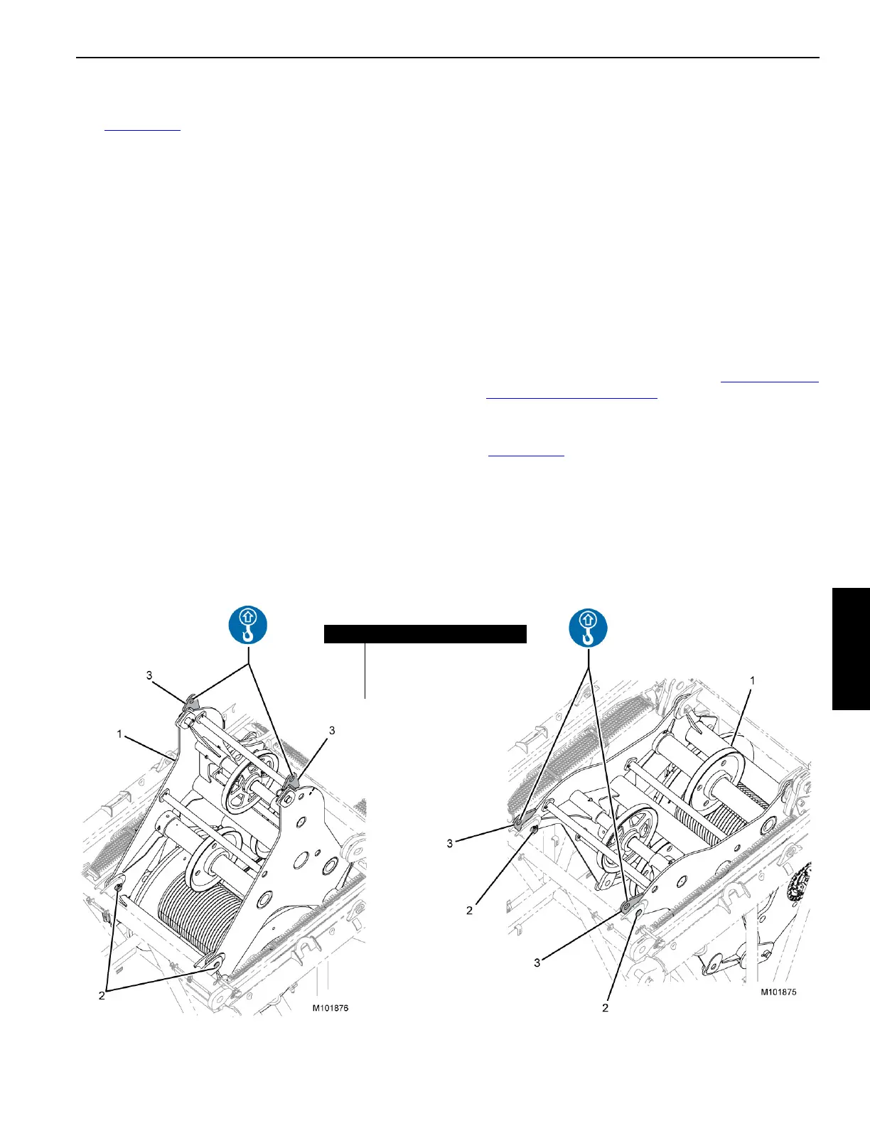
Lowering the Wire Rope Guide
See Figure 4-114 for the following procedure:
1. Attach lifting slings to the lifting lugs (3).
2. Remove safety pins and pins (2, working position).
3. Lower the wire rope guide (1).
4. Install the pins and safety pins (2, stored position).
5. Remove lifting slings.
FIGURE 4-114
STORED POSITION
Working Position
Item Description
1 Wire Rope Guide
2 Safety Pin and Pin (qty 2)
3 Lifting Lug (qty 2)
WORKING POSITION