Manitowoc Published 08-12-19, Control # 224-13_v2 4-153
MLC650 OPERATOR MANUAL SET-UP AND INSTALLATION
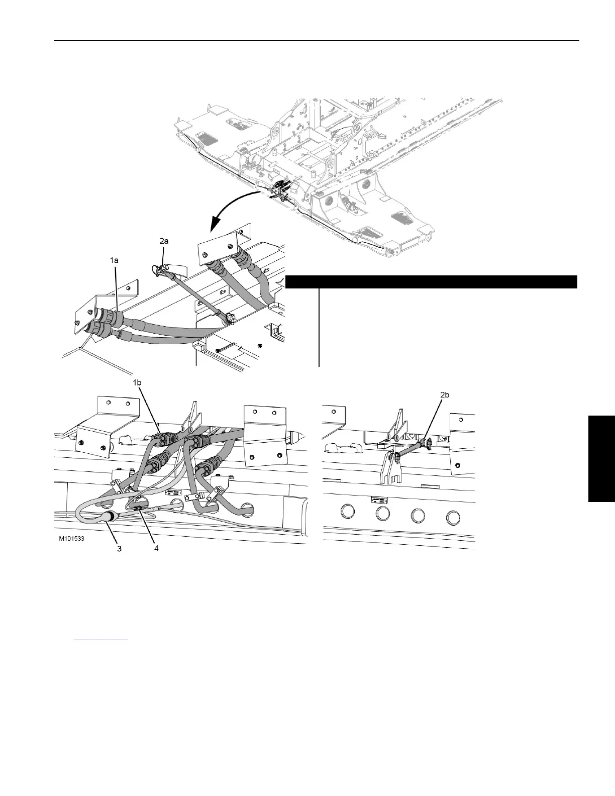
Disconnecting Counterweight Tray
Hydraulics and Electrical Wiring
See Figure 4-120 for the following procedure:
1. With the counterweight tray attached to the assist crane,
disconnect the four hydraulic hoses (1b) from the
working position and connect them to the stored
position.
2. Disconnect the rotating bed electrical connectors
(3 and 4).
3. Disconnect the connecting link (2b) from the working
position and connect it to the rotating bed in the stored
position.
FIGURE 4-120
Item Description
1a Hydraulic Hose (stored position) (qty 4)
1b Hydraulic Hose (working position) (qty 4)
2a Connecting Link (stored position)
2b Connecting Link (working position)
3 Rotating Bed Electrical Connector WVB-1 (connects to WVT1-P1)
4 Rotating Bed Electrical Connector WVB-2 (connects to (WVT2-P1)