Manitowoc Published 08-12-19, Control # 224-13_v2 4-23
MLC650 OPERATOR MANUAL SET-UP AND INSTALLATION
Remove Rotating Bed from Trailer
See Figure 4-19 for the following procedure:
1. Position the trailer (View A) carrying the rotating bed
module at the desired location at the assembly site.
2. Remove all chains and straps used to secure the
rotating bed to the trailer.
Install Alignment Pendants
NOTE: The operator cab must be in the position (View B)
to install the alignment pendant behind the
operator cab frame.
1. Locate the adapter frame (2) and the alignment
pendants (1).
2. Remove the pins and safety pins (3) securing the
alignment pendants in the stored position on the adapter
frame.
3. Align each of the four pendants to the lugs on the
rotating bed (4, View A).
4. Install the pins and safety pins securing the pendants to
the rotating bed (View A).
Deploy Rotating Bed Jacking Cylinders
1. Unfasten the outrigger strut (6) from the stored position.
2. Remove the connecting pin from the rotating bed lug (5,
View B).
3. Swing the outrigger beam assembly (7, View B) from the
stored position to the working position.
4. Install the pins and safety pins to connect the outrigger
strut (6) from the rotating bed lug (5) to the outrigger
beam assembly (7, View C).
5. Remove the jacking cylinder wire locking pin and pin (9)
from the outrigger beam assembly.
6. Remove the wire locking pin and pin from the jacking
cylinder lug (8, View B) which secures the rotating bed
jacking cylinders in the stored position.
7. Use the remote control to lower the rotating bed jacking
cylinder to the working position (View C).
8. Install the pin and wire locking pin (9, View C) to secure
the rotating bed jacking cylinder.
9. Repeat steps 1-8 for each rotating bed jack assembly.
10. Remove the outrigger pad locking pins (10, view B) and
remove the outrigger pads (11, View B) from the stored
position.
11. Install the outrigger pad locking pins (10) in the lugs on
the rotating bed (stored position).
12. Place the outrigger pads on the ground below the
jacking cylinders and remove the U-shaped locking pins
(12, View B) from the outrigger pads.
13. Using the remote control, extend the rotating bed jacking
cylinders (13, View C) until the end of the cylinders align
with the outrigger pads. Adjust pads to align with
cylinders as required.
14. Install the U-shaped locking pins (12, View C).
15. Place unused pins into the stored position for later use.
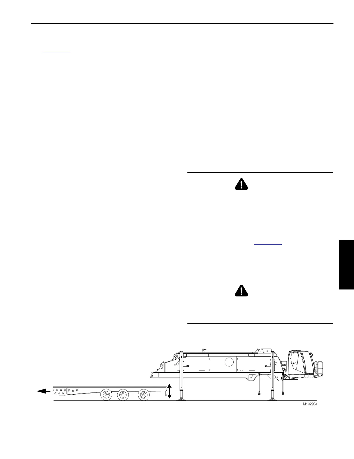
16. Raise the rotating bed until it will clear the trailer and
remove the trailer (see Figure 4-20
).
NOTE: Attach tag lines to the pendants and hold the
pendants away from the rotating bed as the trailer
is removed.
WARNING
Moving Part Hazard!
To avoid serious crushing injury — warn all personnel to
stand clear of jacks.
WARNING
Tipping Hazard!
Avoid tipping the crane over — keep the crane level while
jacking.
FIGURE 4-20
NOTE: A minimum trailer height of
1 168 mm (46 in) is necessary to be
able to deploy the rotating bed
jacking cylinders.