SET-UP AND INSTALLATION MLC650 OPERATOR MANUAL
4-88
Published 08-12-19, Control # 224-13_v2
BOOM AND JIB RIGGING—GENERAL
Assist Crane Requirements
The MLC650 can be used to handle, assemble, and
disassemble the boom and jib components. See the Crane
Weights topic in Section 1 of the MLC650 Operator Manual
for the weights of the boom and jib components.
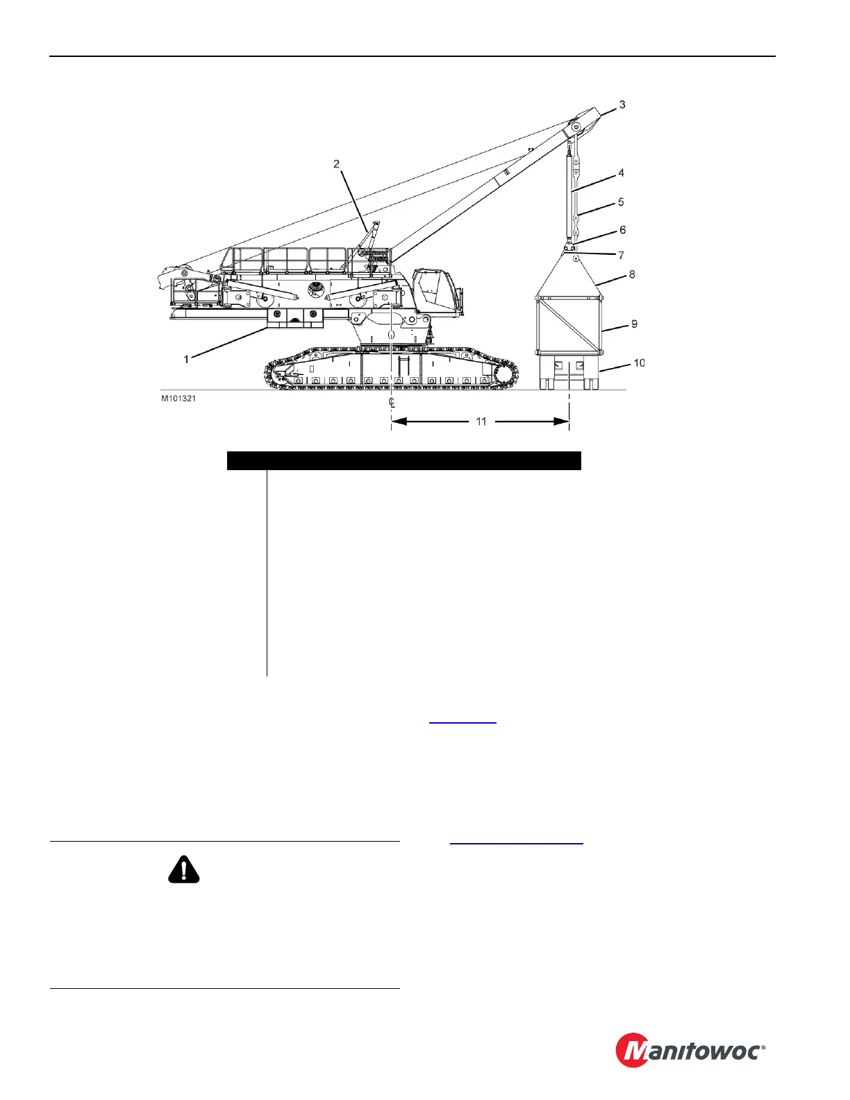
The MLC650 must be in the following configuration
(Figure 4-69
):
• Counterweight Tray and counterweight boxes NOT
INSTALLED.
• Mast-assist arms (2) fully raised.
• Shackles (7) and lifting slings (8) attached to the self-
erect cylinder rod end (6). Reference charts found in
Figure 4-7 on page 4-6
.
• Liftcrane Mast Handling Capacities Chart (9) selected in
configuration screen of the RCL/RCI display.
• Mast (3) operated between the fully extended mast-
assist arms and the maximum allowable radius.
• Radius and capacity limited to that given in the Liftcrane
Mast Handling Capacities Chart at the end of this
section.
Item Description
1 Counterweight Tray Installed or Removed
2 Mast-Assist Arms
3 Mast in Operating Range
4 Self-Erect Cylinder
5Live Mast Straps
6Rod End
72-SH 1 Shackle - 55 t (60.60 USt)
84-SL 4 Slings - 3,80 m (12.50 ft) - 11 340 kg (25,000 lb)
9Insert
10 Trailer
11 See Liftcrane Mast Handling Chart
FIGURE 4-69
DANGER
Falling Load Hazard!
Prevent structural failure of components:
• Do not exceed the lifting capacities given in the
Liftcrane Mast Capacities Chart at the end of this
section.