Manitowoc Published 08-12-19, Control # 224-13_v2 4-131
MLC650 OPERATOR MANUAL SET-UP AND INSTALLATION
Connect Camera and Electric Cables
SeeFigure 4-99, for the following procedure:
1. Pay out the electric cables (10, 13, and 16, View B) from
the cable reels in the 12M insert with sheaves and
connect the electric cables to the cable clips (6, View C)
on the bottom left chord of the boom sections.
2. Connect the electric cables (View B) to the cable
connections (View E) on the boom top.
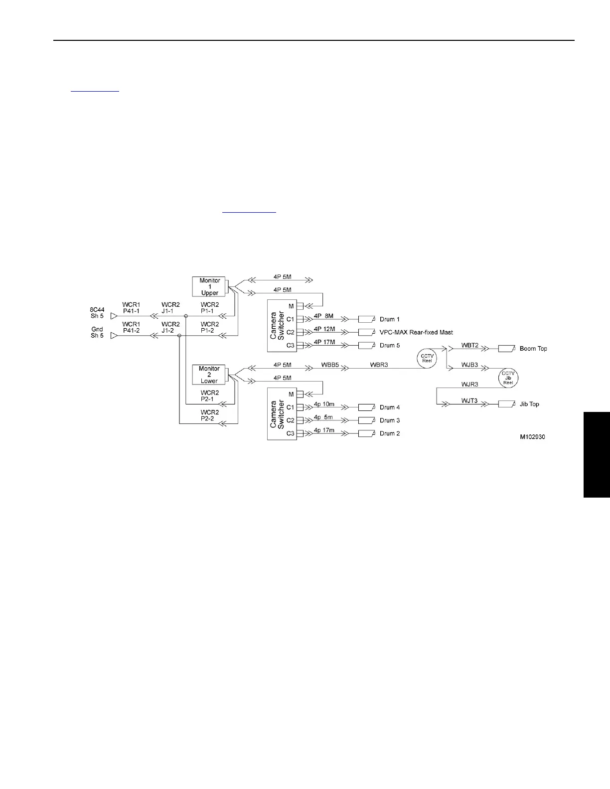
3. Connect the electric cables from the boom butt to the
suggested receptacles in the camera switchers (12,
View A). See the following diagram (Figure 4-100
).
4. Disconnect the CAN terminator (8, View E) from the
CAN NET IN electric cable (8).
5. Connect WN145000 electric cable (15, View E) to the
CAN NET IN electric cable (8).
6. Connect the strain relief cable to the J-bolt.
7. Connect the WBR1 electric cable (14, View C) to the
WBT1 receptacle (9).
8. Connect the CCTV cable (11, WBR3) to the camera
cable (5, WJT3) (this is an option).