Manitowoc Published 08-12-19, Control # 224-13_v2 4-51
MLC650 OPERATOR MANUAL SET-UP AND INSTALLATION
Aligning Rotating Bed to Carbody
See Figure 4-40 for the following procedure:
1. Confirm that the live mast position is at a minimum of
110° to avoid tipping the crane.
2. Fully extend the rotating bed jacking cylinders (5) to
raise the rotating bed to its highest position.
3. Position trailer (1) carrying the adapter frame (2) and
carbody (3) directly in front of the rotating bed (4)
.
4. Position the trailer so the alignment pendant lugs (7) on
the adapter frame are directly under the alignment
pendants (6) hanging from the rotating bed.
5. Retract the rotating bed jacking cylinders just enough so
the four alignment pendants can be pinned to the
adapter frame. Attach the alignment pendants (View B).
NOTE: The rotating bed must not be more than 3° out of
level when retracting the jacks.
6. Remove all tie downs securing the adapter frame and
carbody to the trailer.
7. Raise the rotating bed jacking cylinders so the adapter
frame and carbody are not resting on the trailer, allowing
the adapter frame to self align to the rotating bed.
8. Lower the adapter frame and carbody back onto the
trailer until the mounting holes in the adapter frame and
rotating bed align (see Figure 4-42
).
9. Turn off power to the crane and stop the engine.
NOTE: Reference "Connecting/Disconnecting Hydraulic
Hoses and Electric Cables" on page 4-10 for more
information.
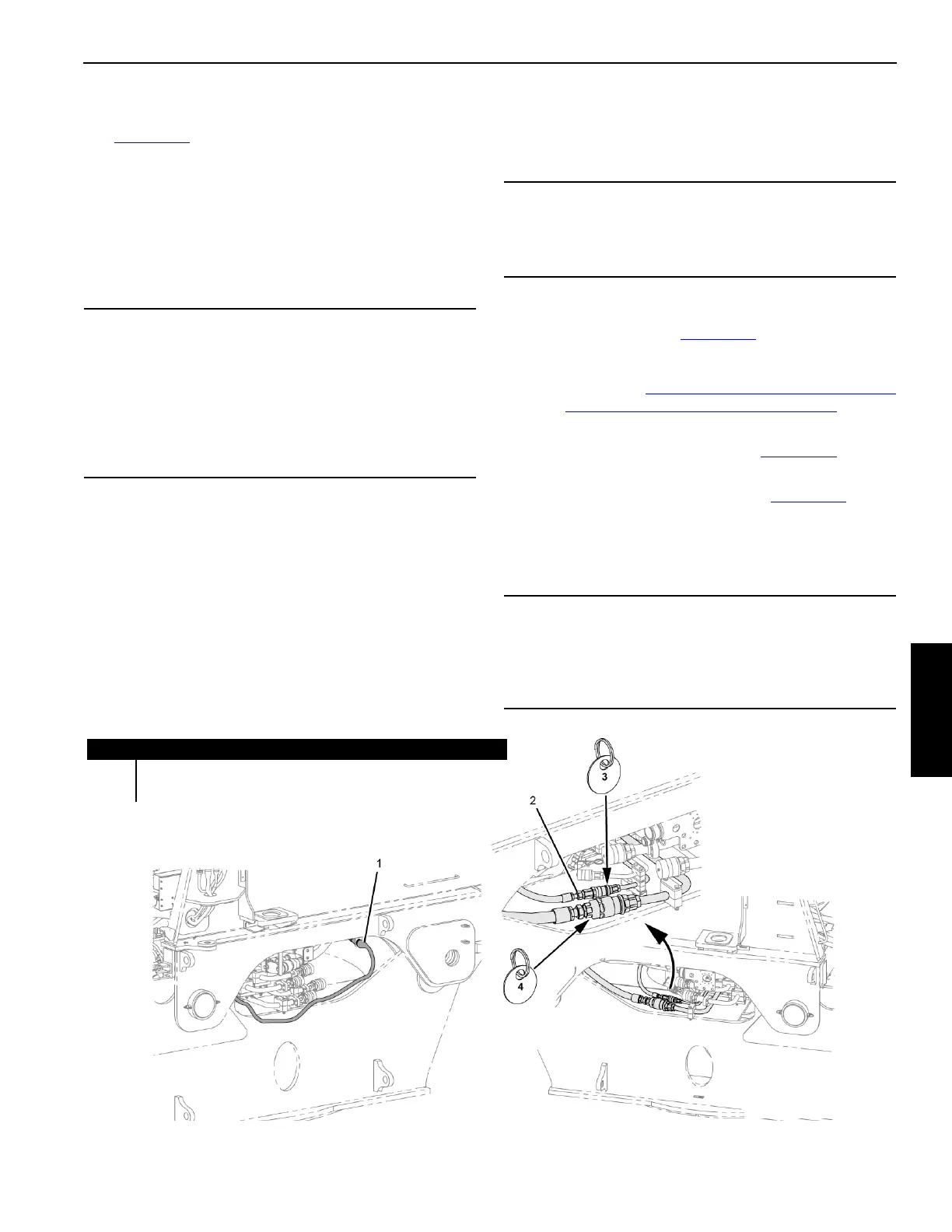
10. Connect the electric cable (1, Figure 4-41
) to the
connector on the left side of the rotating bed.
11. Connect the two hydraulic hoses (2, Figure 4-41
) on the
right side (bottom or lower) from the adapter frame to the
rotating bed to provide hydraulic power to the front pin
puller cylinders.
12. Turn on crane power and start engine.
CAUTION
Equipment Damage!
Use extreme care when backing the trailer into position:
• Do not hit the jacks with the trailer.
• Do not hit the rotating bed with the adapter frame.
Provide a signal person to give instructions to the truck
driver.
CAUTION
Overweight Hazard!
Do not lower the entire weight of the rotating bed onto the
adapter frame. Weight may exceed trailer capacity.
CAUTION
Equipment Damage!
Install the two hydraulic hoses and the electric cable
before attempting to install the adapter frame to rotating
bed pins.
Item Description
1 Adapter Frame Electrical Cable (WFC1 connects to WRF2-J5)
2 Hydraulic Connections #3 and #4
LEFT SIDE OF CRANE
RIGHT SIDE OF CRANE
FIGURE 4-41