SET-UP AND INSTALLATION MLC650 OPERATOR MANUAL
4-164
Published 08-12-19, Control # 224-13_v2
Removing First Crawler (continued)
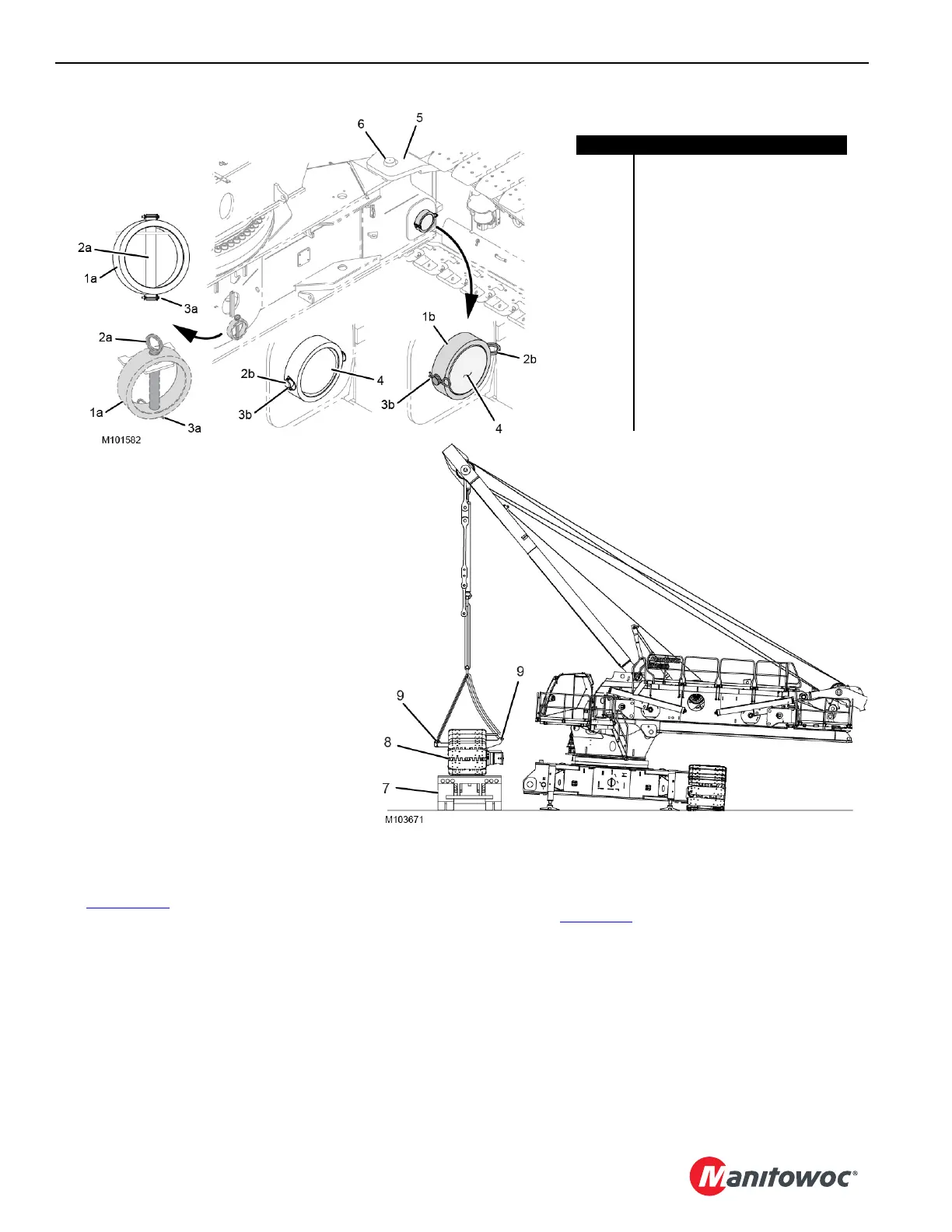
See Figure 4-128 for the following procedure:
10. Remove the hair pin cotter or safety pin (3b), retaining
pin (2b), and collar (1b) and place them in the stored
position. Repeat the procedure for the other pin on the
same crawler.
11. Using the remote control, disengage the crawler pins
(4).
NOTE: The crawler pins must be shipped in the retracted
position to meet shipping width requirements.
12. Retract the self-erect cylinder, raising the crawler
hook (5) from the carbody pin (6).
Reference Table 4-3
for swing limits during crawler
disassembly.
13. Position a trailer (7) next to the crane. Place and secure
the crawler assembly (8) onto the trailer with blocking
and secure the crawler to the trailer.
14. Remove the slings from the lifting brackets (9) on the
crawler frame.
15. Remove the crawler assembly and trailer.
FIGURE 4-128
Item Description
1a Collar (stored position)
1b Collar (working position)
2a Retaining Pin (stored position)
2b Retaining Pin (working position)
3a Hair Pin Cotter or Safety Pin
(stored position)
3b Hair Pin Cotter or Safety Pin
(working position)
4 Crawler Pin (qty 2)
5 Crawler Hook
6 Carbody Pin
7 Trailer
8 Crawler Assembly
9 Lifting Bracket (qty 3)
STORED
POSITION
WORKING
POSITION
OR
OR