Manitowoc Published 08-12-19, Control # 224-13_v2 4-53
MLC650 OPERATOR MANUAL SET-UP AND INSTALLATION
Attaching Rotating Bed to Adapter Frame
See Figure 4-42 for the following procedure:
1. Confirm the alignment of the pin holes on the rotating
bed and the adapter frame.
2. Engage the front adapter frame pins (3a) to the rotating
bed.
3. Engage the rear rotating bed pins (1a) to the adapter
frame.
4. Remove the hair-pin cotters, pins, and collars (2a) from
the stored position.
5. Install the hair-pin cotters, pins, and collars (2b) onto the
adapter frame pins (3b) and rotating bed pins (1b).
6. Extend the rotating bed jacking cylinders (4) so the
carbody clears the trailer.
NOTE: With no blocking under the outrigger pads and with
the carbody attached to the rotating bed, the
jacking cylinders can lift the carbody to clear a
maximum trailer height (5) of 1 168 mm (46 in).
7. Remove the trailer, using extreme care not to hit the
rotating bed jacking cylinders.
8. Retract the rotating bed jacks until the bottom plate of
the carbody is 610 mm (24 in) from the ground.
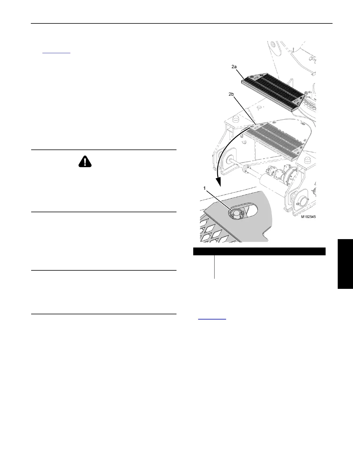
Removing Carbody Cavity Platform
See Figure 4-43 for the following procedure:
The carbody cavity platforms (2a) on each side must be
removed before the crawlers can be installed or damage will
occur.
1. Remove the quick release pins (1).
2. Remove the carbody platforms using hand holes in the
platform and set aside until after crawler installation is
complete.
WARNING
Moving Part Hazard!
To avoid serious crushing injury—warn all personnel to
stand clear of jacks.
Crane Tipping Hazard!
Keep the crane level while jacking.
CAUTION
Equipment Damage!
Use extreme care when removing the trailer.
Do not hit the jacks with the trailer. Provide a signal
person to give instructions to the truck driver.
Item Description
1 Quick Release Pin (qty 4)
2a Carbody Cavity Platform (removed) (qty 2)
2b Carbody Cavity Platform (working position) (qty 2)
FIGURE 4-43