Manitowoc Published 08-12-19, Control # 224-13_v2 4-81
MLC650 OPERATOR MANUAL SET-UP AND INSTALLATION
Installation of the Hydraulic Hoses
See Figure 4-64 for the following procedure:
1. Activate the pinions using the remote control and
confirm that the drive pinions rotate in the same and
correct direction and then deactivate the pinions.
NOTE: Only one of the pinions may rotate, this is a normal
condition. Confirm that at least one pinion rotates in
the correct direction.
2. With the counterweight tray still attached to the assist
crane, disconnect the four hydraulic hoses (1a) from the
stored position and connect them to the working position
(1b).
The hoses and the corresponding couplers are tagged
with numbers. Match the numbers to ensure proper
hose connection.
3. Connect the electrical connections (3 and 4) from the
rotating bed to the counterweight tray.
Align the Counterweight Tray to the Pinions
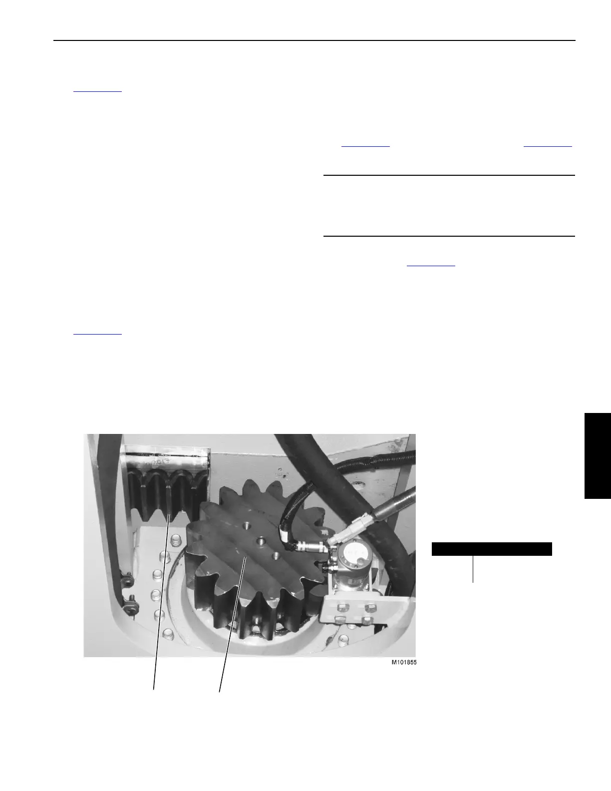
See Figure 4-65 for the following procedure:
1. Slowly pull the counterweight tray forward with
assistants, taglines, and assist crane until the drive
pinion teeth contact the first gear rack teeth.
With the tray still attached to the assist crane, relax the
rigging just enough to be sure that the majority of the
tray weight is supported by the rotating bed.
2. Using the remote control, activate the pinion drives (1) to
slowly move the counterweight tray forward to be sure
that the drive pinions are meshing properly with the
rotating bed gear racks (2). Stop the counterweight tray
movement when the connecting link aligns.
3. Move the connecting link from the stored position (2a,
Figure 4-64
) to the working position (2b, Figure 4-64)
and install pins.
4. Slowly drive the tray forward to a point where the large
stop blocks (8, Figure 4-63
) can be installed and install
the blocks and pins.
NOTE: Speed control is variable for the counterweight tray.
5. Disconnect the assist crane from the counterweight tray.
6. See the MLC650 Main Display Operation manual for
counterweight tray calibration instructions.
CAUTION
Parts Damage!
Connecting link must be installed before continuing or
damage will occur.
2
1
Item Description
1 Drive Pinion
2 Gear Rack
FIGURE 4-65