Manitowoc Published 08-12-19, Control # 224-13_v2 4-181
MLC650 OPERATOR MANUAL SET-UP AND INSTALLATION
Removing Drum 3
An assist crane is required to lift the drum from the rotating
bed.
NOTE: The assist crane must be capable of lifting 6 000 kg
(3,200 lb) to a height of approximately 6 m (20 ft)
above the ground.
Reference Section 1 of this manual for actual weights of
components.
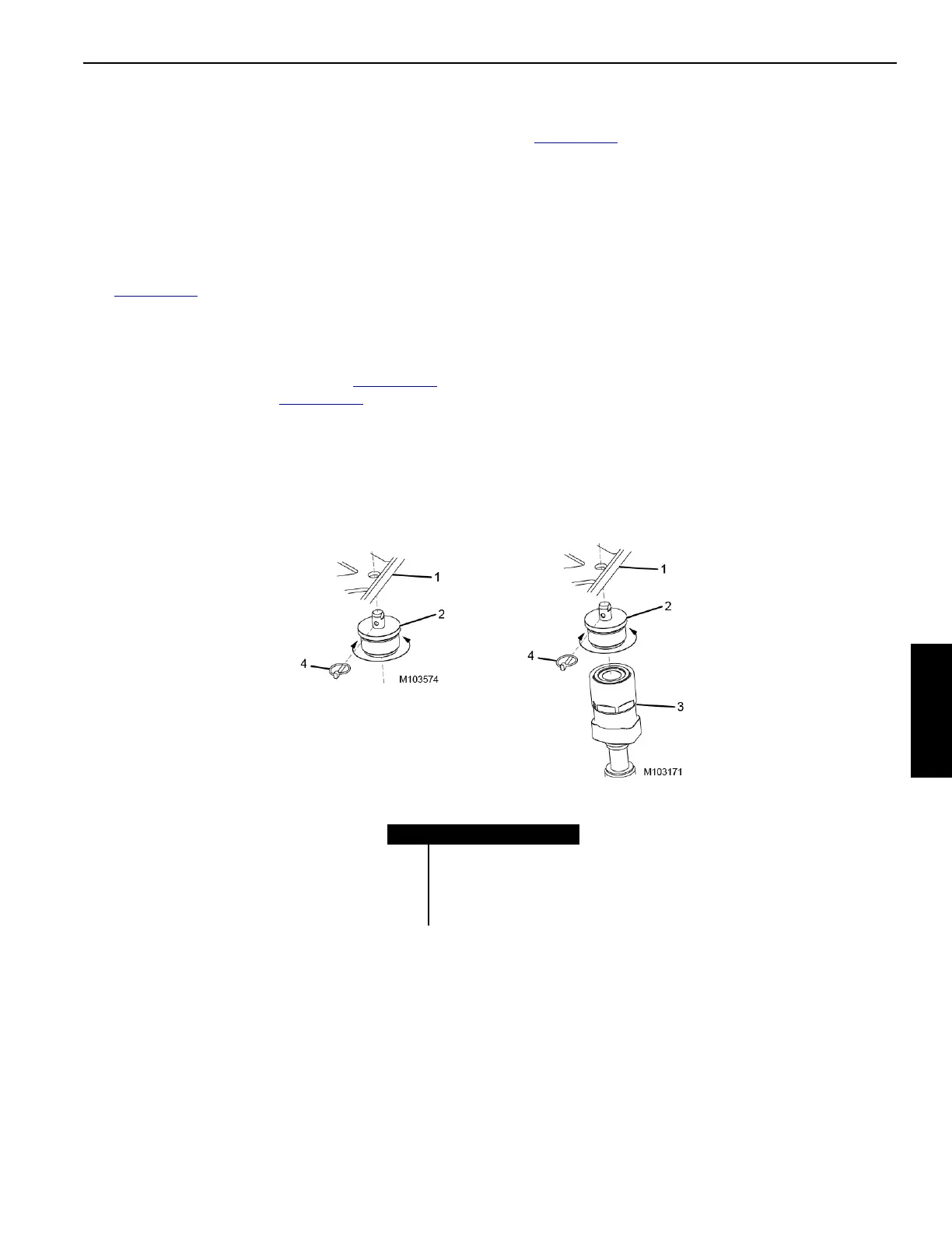
See Figure 4-139
for the following procedure:
1. Remove the locking pin (4) and the mounting plug (2)
from the hose storage bracket (1) as shown in the stored
position.
2. Disconnect the hydraulic hoses (10, Figure 4-138
) from
the hydraulic couplers (9, Figure 4-138).
3. Screw the mounting plug (2) into the hose coupler (3).
Align the mounting plug pin with the hose storage
bracket (1) and insert the locking pin as shown in the
shipping position.
4. Repeat for the remaining hoses.
See Figure 4-138
for the following procedure:
5. Disconnect the electrical cable (8) from the drum
assembly (1) and store the cable.
6. Attach the
SL 4 slings (2) to the hook of the assist crane.
7. Connect the other end of the slings to the lifting lugs (3)
on the drum assembly with the
SH 2 shackles (4). Raise
the drum slightly to reduce pressure on the pins.
8. Remove the locking pins and pins (7) and set aside.
9. Remove the front and rear pins (5 and 6).
10. Slowly lift the drum assembly from the rotating bed and
place onto the trailer.
11. Disconnect the shackles and the slings from the lifting
lugs on the drum assembly.
12. Block and tie down the drum, securing the assembly to
the trailer.
Item Description
1 Hose Storage Bracket
2 Mounting Plug
3 Hose Coupler
4 Locking Pin
FIGURE 4-139
STORED POSITION
SHIPPING POSITION