Manitowoc Published 08-12-19, Control # 224-13_v2 4-55
MLC650 OPERATOR MANUAL SET-UP AND INSTALLATION
Deploying Carbody Jacking Cylinders
See Figure 4-44 for the following procedure:
1. Remove the safety pin and pin (6, View A) from the jack
lug (7, View A) securing the carbody jacking cylinders
(3, View A) to the carbody (2).
2. Rotate the carbody jacking cylinders (3, View A) out from
the storage position to the working position (3, View B).
3. Remove the safety pin and pin from the strut (5, View A).
4. Install the strut (5, View B) to the jack lug (7, View B) and
to the carbody lug (8, View B). Insert the pins and safety
pins (6, View B).
5. Remove the outrigger pad (4) from the shipping position
and place on the ground below the jack rod (View B).
NOTE: Each jack pad weighs approximately 40 kg (90 lb).
6. Using the remote control, extend the carbody jacking
cylinder (3, View C) until the cylinder rod engages the
outrigger pad.
7. Repeat steps 1 – 6 for each carbody jacking cylinder
8. Retract the rotating bed jacking cylinders and move to
the stored position (see Figure 4-46 on page 4-56
).
9. Extend the carbody jacking cylinders (3, View D) —
keep the crane level until the carbody is approximately
722 mm (28 in) above the ground and the small
diameter jack rod is fully retracted.
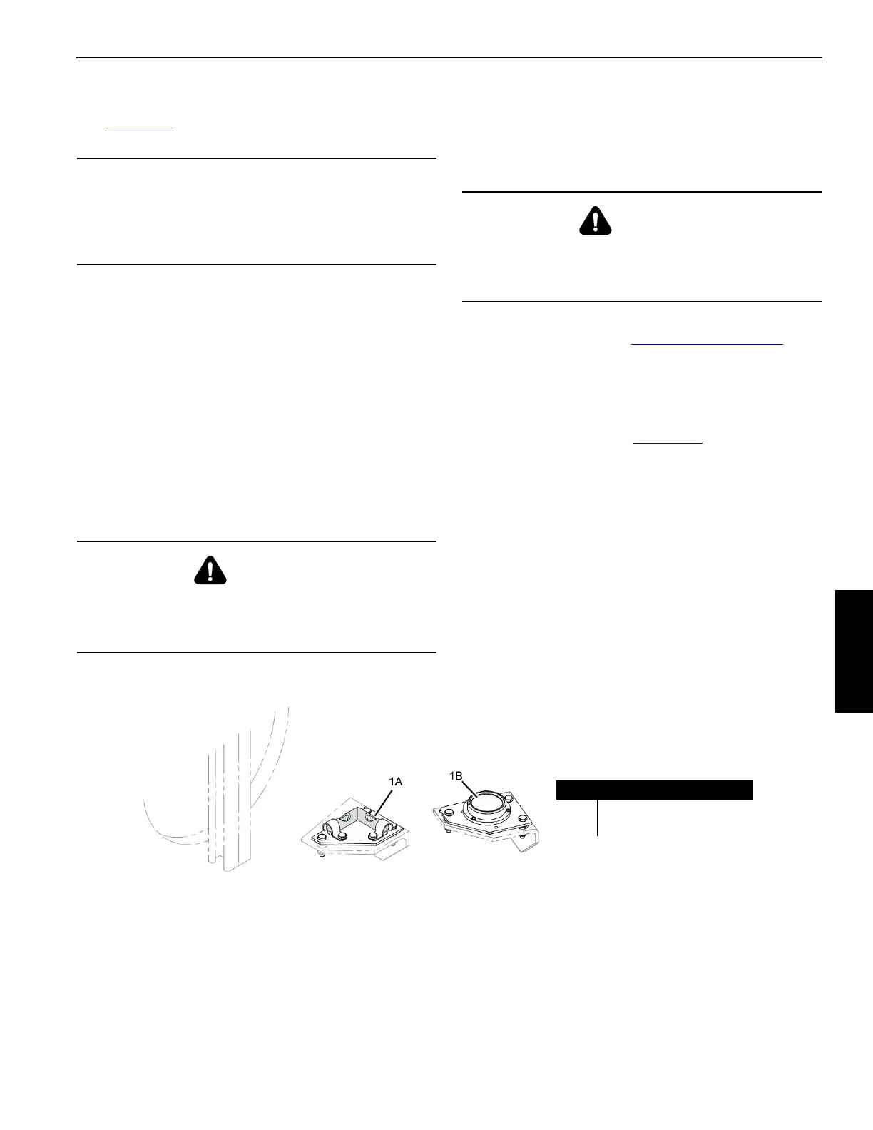
NOTE: A level (1A or 1B, Figure 4-45
) is provided on the
carbody.
CAUTION
Avoid Structural Damage
Do not extend the carbody jacking cylinders when they
are stored. Serious structural damage will occur to the
carbody and jacks.
WARNING
Moving Part Hazard!
To avoid serious crushing injury — warn all personnel to
stand clear of the jacking cylinders.
WARNING
Tipping Hazard!
Avoid tipping the crane over — keep the crane level while
jacking.
FIGURE 4-45
Item Description
1A 2-Way Level
1B Circular Level
OR