Manitowoc Published 08-12-19, Control # 224-13_v2 4-41
MLC650 OPERATOR MANUAL SET-UP AND INSTALLATION
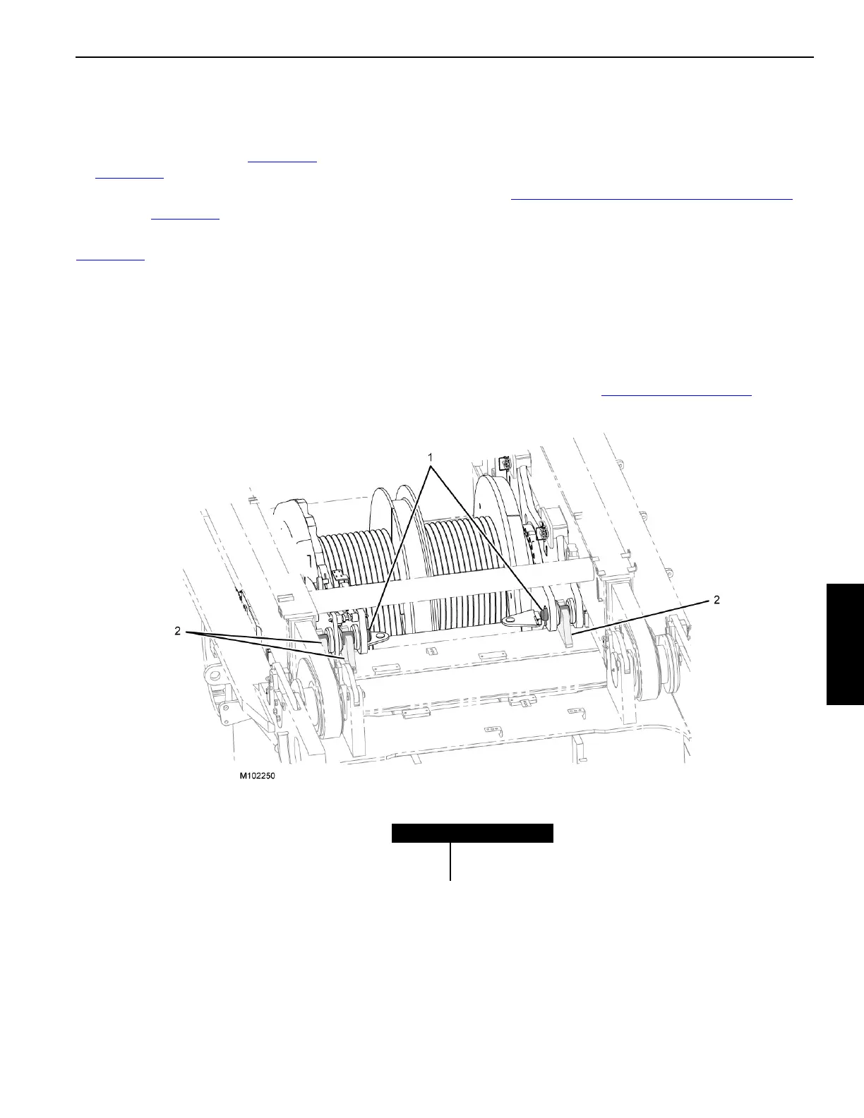
Secure the Backhitch/Gantry Assemblies
With the assist crane still attached to the live mast assembly,
slowly lower the mast assembly to the rotating bed until the
live mast hoist drum pins (1, Figure 4-34
) engage the hooks
(2, Figure 4-34
) on the rotating bed.
Ensure that the gantry is fully engaged with the rotating bed
pockets (11, Figure 4-33
).
When installing the backhitch/gantry assemblies reference
Figure 4-33
for the following procedure.
1. Remove the gantry pin retention brackets (9a) and place
them in the stored position (9b).
2. Install the operating pins (8) to the working position
using the pin puller cage (10) and the hand-held pin
puller:
See "Connect Hand-Held Pin Puller" on page 4-37
for
information on using the pin puller.
3. Secure the operating pins (8) with keeper pins (7b) and
hitch pins.
4. Remove pins 3, 5, and 6 from the shipping position and
place them into the stored position.
5. Remove the backhitch link pin (2b) from the shipping
position before raising the mast.
The backhitch link pin will be inserted into the working
position but will require lifting the backhitch assembly to
align the holes (see Figure 4-37 on page 4-46
).
FIGURE 4-34
Item Description
1 Hoist Drum Pins
2 Hooks