SET-UP AND INSTALLATION MLC650 OPERATOR MANUAL
4-212
Published 08-12-19, Control # 224-13_v2
Wire Rope Specifications
Refer to the Wire Rope Specifications chart in the Capacity
Chart Manual for:
Parts of the line required to handle desired load
Wire rope length required for various boom lengths and parts
of line
Maximum spooling capacity of load drums
Load Block Reeving
For reeving of the lower boom point, see the Reeving
Diagrams at the end of this section.
Reeving in any manner other than shown can result in
excessive block twist.
Dead End Locations
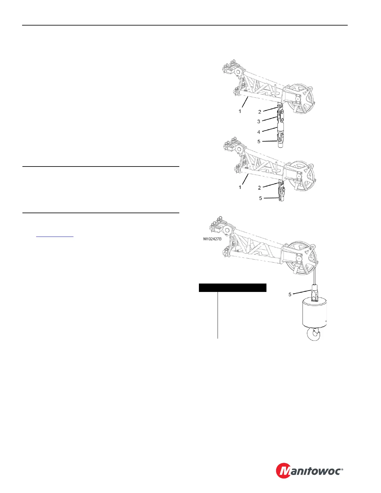
See Figure 4-166 for the upper boom point dead end
locations and required hardware.
See the Boom Rigging Drawing for the lower boom point
dead end locations and required hardware.
All hardware is stored in the job boxes provided with the
crane.
CAUTION
Wire Rope Damage!
Do not hoist the load block closer to the boom point than
shown in the reeving diagrams. Improper fleet angle or
contact with other parts can damage the wire rope.
FIGURE 4-166
Upper Boom Point Multiple Parts of Line
Upper Boom Point Single Part of Line
Item Description
1 Upper Boom Point
2 Dead-End Link
3Link
4Swivel
5 Button Socket –
28 mm or 32 mm