Manitowoc Published 08-12-19, Control # 224-13_v2 4-163
MLC650 OPERATOR MANUAL SET-UP AND INSTALLATION
Removing First Crawler
See Figure 4-126 for the following procedure:
1. Extend the self-erect cylinder rod to the maximum
length. Attach a
SH 1 shackle (1, View A) to the rod end
and a SL 5 sling
(2, View A) to the SH 1 shackle.
2. Attach a SH 1 shackle to the SL 5 sling (View A), SL 1
sling (3), and two SL 2 slings (4).
Reference the lifting sling and shackle chart found in
Figure 4-7 on page 4-6
.
3. Position the live mast and self-erect cylinder above the
crawler.
4. Install chain slings (7) from the crawler frames to the
crawler shoes to prevent excessive crawler track sag.
NOTE: Some sag must be allowed to prevent interference
between the carbody and crawler pads.
5. Remove the safety pins and pins (5), rotate the crawler
lifting brackets (6a) from the stored position to the
working position, and install the pins and safety pins.
6. Using the remote control extend the carbody jacking
cylinder on the side of the crawler to be removed high
enough for the crawler pads to clear the ground.
NOTE: Do not extend the carbody jacks more than
needed.
7. Remove the cotter pin and pin (10) from the outside
crawler lifting brackets (6b). Position two SL 2 slings
inside the crawler lifting brackets, place the pin through
each sling and bracket, and install the cotter pin.
8. Remove the cotter pin and pin (11) from the inside
crawler lifting bracket. Position one SL 1 sling inside the
bracket, install the pin through the sling and bracket, and
install the cotter pin.
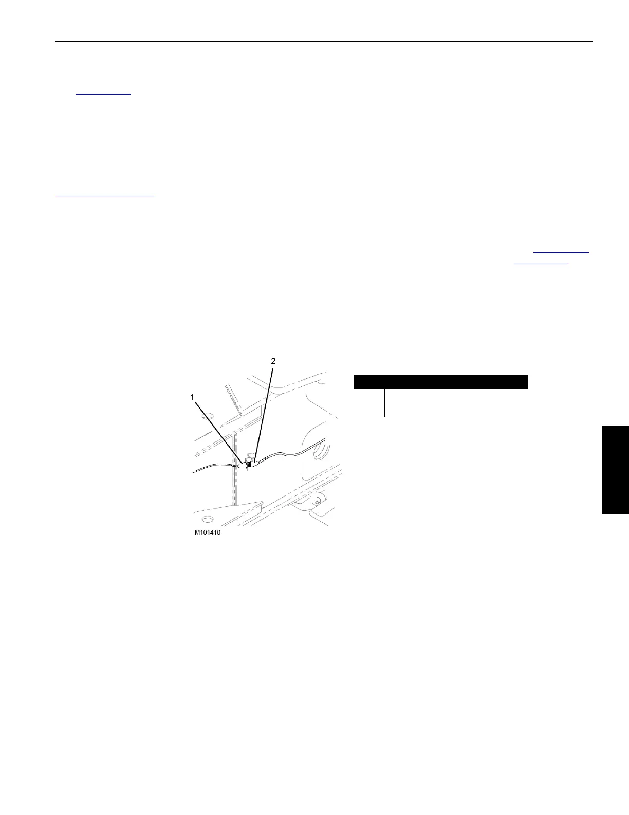
9. Disconnect the crawler electrical cable (2, Figure 4-127
)
from the carbody electrical cable (1, Figure 4-127
) and
store the cables on the appropriate cable holder using
cable ties.
FIGURE 4-127
Item Description
1 Carbody Electrical Cable (WLC2)
2 Crawler Electrical Cable (WLL1-P1)