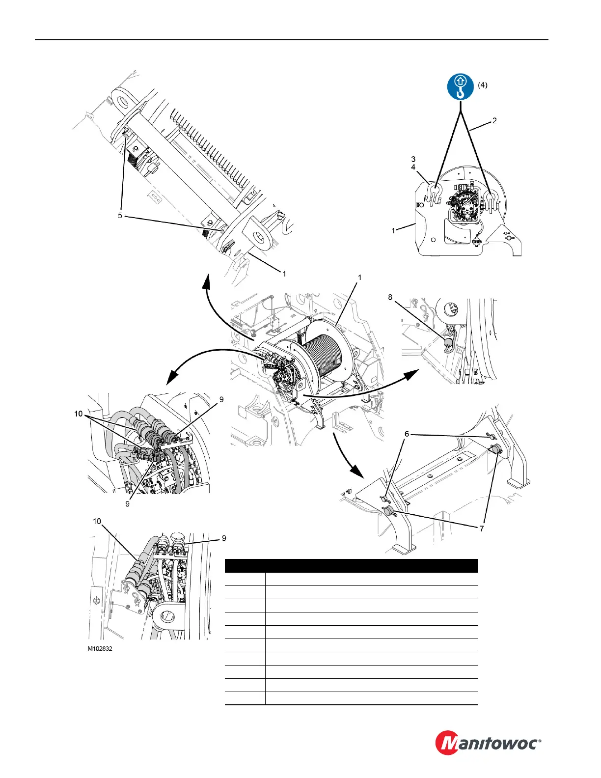
Home
Manitowoc
Construction Equipment
MLC650
Manitowoc MLC650 User Manual
5
of 1
of 1 rating
360 pages
Give review
Manual
Specs
To Next Page
To Next Page
To Previous Page
To Previous Page
Loading...
SET-UP AND INSTALLATION
MLC650 OPERA
TOR MANUAL
4-32
Published 08-12-19, Control # 224-1
3_v2
FIGURE
4-26
Vie
w A
WORKING POSITION
STORED POSITION
Item
Description
1
Drum 3 Assembly
24
-
SL
4
- Sli
ngs - 3,80
m (12.5
ft) - 1
1
340
kg (25,000
lb)
3
Lifting Lug (4)
44
-
SH
2
-
Shackles - 17
t (18.70
USt
)
5
Rear Pins
6
Front Pins
7
Pins with Safety Pins (qt
y 2)
8
Electric Cable (WRF1-P1)
9
Hydraulic Couplers (qty 4)
10
Hydraulic Hoses (qty 4)
167
169
Table of Contents
Default Chapter
5
Table of Contents
5
Section 1
13
Crane Data
13
Crane Weights
13
Outline Dimensions
13
Change of Ownership Registration
13
Manitowoc Dealer
13
Crane/Attachment Identification
13
Crane Orientation
13
Identification and Location of Components
14
VPC and VPC-MAX
16
English and Metric Conversions
16
Direct Conversion
16
Inverse Conversion
16
Section 2
19
Continuous Innovation
21
Nameplates and Decals
21
Safety Messages
21
General
21
Safety Alert Symbol
21
Signal Words
21
Symbol Identification
21
Safety and Information Signs
23
Maintaining Signs
23
Ordering Signs
23
Crane Access Points
26
General
26
Getting on or off Crane
26
Personal Fall-Protection
27
Operator Manual/Capacity Chart Storage
28
General
28
Storing Manuals
28
Safe Operating Practices
29
General
29
Read Operator Manual
29
Operator Qualifications
29
Operator Conduct
29
Handling Load
31
Size of Load
31
Attaching Load
31
Lifting/Moving Load
32
Multiple Load Line Operation
33
Signals
34
Holding Load
34
Safety Devices
35
Operational Aids
35
Category 1 Operational Aids
35
Category 2 Operational Aids
36
Assembling, Disassembling, or Operating Crane Near Electric Power and Transmission Lines
37
Electrocution Hazard
37
Set-Up and Operation
37
Electrocution Hazard Devices
38
Electrical Contact
38
Refueling
39
Fire Extinguishers
39
Accidents
39
Safe Maintenance
39
Maintenance Instructions
39
Safe Maintenance Practices
39
Environmental Protection
41
Boom Disassembly Safety
43
General
43
Location
43
Pin Removal
43
Disassembly Precaution
43
Personnel Handling Policy
44
Pedestal/Barge Mounted Cranes
45
Pedestal Mounted Crane
46
Barge Mounted Crane
46
Definition
46
Examples
46
Capacity Charts for Barge Mounted Crane
47
Shock Loading Caused by Barge Dynamics
47
Operation on Barge
47
Barge Mount Definitions
48
Inspection of Barge-Mounted Crane
48
Transporting Crane on Barge
48
Section 3
49
Standard Hand Signals for Controlling Crane Operations
52
Symbols Used on Control Consoles
54
Symbols Used on Remote Control
57
Operating Controls
62
Left Console
66
Right Console
68
Operation of Diverting Circuits
77
Foot Pedals
78
Seat Controls
79
Climate Control Keypad
80
Other Operator Aids
81
Boom Angle Indicator
81
Crane Capacity Beacons
81
Upperworks Level
81
Crane Cameras
84
Crane Camera Monitor
85
Motion Warning Lights and Alarms
86
Service Lights
88
Remote Control Activation
90
Remote Control Operation
92
Operating Limits Identification and Operation
98
Bypassing Limits in Luffing Jib Setup Mode
104
Resetting Luffing Jib Limits
105
Drum and Control Handle Identification
106
Right Cab Window Operation
108
Closing Window
108
Opening Window for Ventilation
108
Operator's Cab Emergency Exit
108
Cab Door Adjustment
108
Cab Tilt Adjustment
109
Operating in Wind
109
Crawler Blocking
110
Intermediate Suspension
110
Preparing Crane for Operation
110
Startup Procedures
111
Operating Procedures
115
VPC Operation
115
Boom Hoist Operation
116
Luffing Hoist Operation
117
Swing Operation
118
Load Drum Operation
121
Travel Operation
122
Shutdown Procedure or Leaving the Crane Unattended
124
Changing Counterweight with Boom/Jib in Air
125
Vpc
125
Vpc-Max
125
Cold Weather Operation
127
Crane Limitations
127
Wire Rope
127
Cold Weather Starting Aid
127
Cooling System
127
Batteries
127
Engine Oil, Gear Oil, and Hydraulic Oil
127
Cold Weather Heater Package
129
Turning Heaters on
129
Turning Heaters off
129
AC Operation
131
Installing APU
131
Turning on AC Powered Components
131
Turning off AC Powered Components
131
Removing APU
132
Section 4
137
Boom and Jib Assembly Drawings
137
Liftcrane Mast Handling Capacities
137
Optional Attachments
137
General Safety
137
Crane Orientation
137
Assembling and Disassembling Notes
137
Assembly and Disassembly Area
138
Accessing Parts
138
Retaining Connecting Pins
138
Crane Weights and Shipping Data
138
Personal Fall-Protection
139
Handling Components
139
Crane Assembly Components
141
Parts Box
141
Swing Limits
144
Hydraulic Hose Identification
146
Connecting/Disconnecting Hydraulic Hoses and Electric Cables
146
Hose and Cable Cleanliness
146
Pin and Connecting Hole Cleanliness
146
Tightening Hydraulic Couplers
146
Remote Control
148
Activating the Remote Control
149
Starting Engine with Remote Control
149
Rotating Bed Jacking Cylinders Function
149
Setup Mode
149
Identification and Location of Components
150
Crane Assembly
151
Remove Cab Window Covers
151
Perform Pre-Start Checks
153
Electric System
153
Hydraulic System
153
Gear Boxes
153
Deploy Operator Cab Platform
155
Start Engine
155
Remove Rotating Bed from Trailer
159
Install Alignment Pendants
159
Deploy Rotating Bed Jacking Cylinders
159
Install Operator Cab Rear Platform
160
Install Operator Cab Ladder
161
Overview of Rotating Bed Platforms and Handrails
163
Deploy Rotating Bed Platforms
165
Install Platforms, Ladders and Handrails
167
Install Drum 3
169
Activate Auxiliary Hydraulic System
170
Connect Hand-Held Pin Puller
173
Install the Live Mast
174
Secure the Backhitch/Gantry Assemblies
177
Secure the Live Mast Hoist Drum
179
Disconnect the Live Mast Straps
179
Connect the Live Mast Hydraulic and Electrical
181
Activate Setup Mode
182
Raise Live Mast to Operating Position
182
Deploy the Self-Erect Cylinder
185
Use the Mast as a Boom
185
Aligning Rotating Bed to Carbody
187
Attaching Rotating Bed to Adapter Frame
189
Removing Carbody Cavity Platform
189
Deploying Carbody Jacking Cylinders
191
Storing Rotating Bed Jacking Cylinders
192
Installing Hydraulic Connections
193
Deploying Operator Cab (Working Position)
196
Installing Crawlers
197
Storing Carbody Jacking Cylinders
203
Installing Carbody Cavity Platform
204
Installing Crawler Drive Shafts
207
Installing Carbody Platforms
208
Installing Carbody Ladders and Handrails
209
Installing Front Platforms, Ladders, and Handrails from Rotating Bed and Cab
211
Installing Counterweight Tray
213
Installation of the Hydraulic Hoses
217
Align the Counterweight Tray to the Pinions
217
Remove Counterweight Boxes from Trailer
219
Assemble Boom and Jib
219
Install Counterweight Boxes
219
Boom and Jib Rigging-General
224
Assist Crane Requirements
224
Blocked Crawlers
225
Boom Handling with Mast
225
Assembly Drawings
225
Identifying Boom and Jib Components
225
Handling Boom and Jib Sections
227
Boom Ladders
229
General
229
Removing Ladders from Insert
229
Installing Ladders on Boom Inserts
229
Storing Ladders in Insert
229
Boom Assembly
231
Assemble Boom Inserts and Top
231
Raise Boom Top Wire Rope Guide
241
Install/Remove Lower Boom Point
243
Install Position Light and Wind Speed Indicator
245
Connect Boom Straps
247
Install Upper Boom Point
249
Connect Terminator/Shorting Plugs at Boom Top
249
Prepare 4M Insert
253
Raise Wire Rope
253
Connect 4M Insert to Boom Butt
255
Lower Carbody Platform
255
Connect Boom Butt to Crane
257
Lower Boom Butt and 4M Insert
259
Raise Carbody Platform
259
Connect Hydraulic Hoses from Crane to Boom Butt
261
Connect Electric Cables from Boom Butt to Crane
261
Connect 4M to Boom
263
Connect Mast Straps to Boom Straps
265
Deactivating Setup Mode
265
Connect Camera and Electric Cables
267
Install the Boom Load Lines
269
Install the Boom Block-Up Limit Components
269
Prepare Intermediate Suspension Pendants
271
Raise Boom
272
Pre-Raising Checks
272
Boom Raising Procedure
272
Shipping Crane Components
273
Crane Disassembly
274
Preparing Crane
274
Lowering Boom
274
Removing Block-Up Limit Components
274
Storing the Load Lines
274
Removing Boom Top Cameras
274
Disconnecting Boom Butt Electric Cables
274
Disconnecting Boom Butt Hydraulic Hoses
274
Activating Setup Mode
277
Disconnecting Mast Straps from Boom Straps
277
Lowering Carbody Platform
277
Disconnecting Boom from 4M Insert
279
Deploying Self-Erect Cylinder
279
Removing Boom Butt and 4M
280
Separating 4M Insert from Boom Butt
283
Lowering the Wire Rope Guide
283
Loading Boom Butt
284
Raising Carbody Platform
284
Disassembling Boom
285
Removing Counterweight Boxes
286
Preparing Counterweight Tray for Removal
288
Disconnecting Counterweight Tray Hydraulics and Electrical Wiring
289
Removing Counterweight Tray
291
Removing Carbody Platforms
293
Removing Carbody Cavity Platforms
293
Disconnecting and Storing Drive Shafts
295
Deploying Carbody Jacking Cylinders
297
Removing First Crawler
299
Removing First Crawler (Continued)
300
Removing Second Crawler
303
Deploying Rotating Bed Jacking Cylinders
305
Storing Carbody Jacking Cylinders
307
Installing Carbody Cavity Platforms
307
Disconnecting Carbody from Rotating Bed
309
Disconnecting Hydraulic Hoses
310
Removing Carbody and Adapter Frame from Rotating Bed
311
Storing Self-Erect Cylinder
313
Securing Live Mast, Gantry, and Backhitch
315
Removing Drum 3
317
Disconnecting Live Mast Hydraulics and Electrical Connectors
319
Removing Live Mast
319
Removing Rotating Bed Handrails and Rear Platform
323
Removing Front Platform and Ladders from Rotating Bed and Cab
324
Storing Rotating Bed Platforms
326
Moving Operator Cab (Shipping Position)
328
Removing Operator Cab Ladder
329
Removing Operator Cab Rear Platform
330
Storing Operator Cab Front Platform
331
Securing Operator Cab
332
Extending Rotating Bed Jacking Cylinders
333
Lowering Rotating Bed Jacking Cylinders
335
Installing Cab Window Covers (if Equipped)
336
Wire Rope Installation
337
Wire Rope Specifications
337
Wire Rope Storage
337
Seizing and Cutting Wire Rope
337
Anchoring Wire Rope to Drum
338
Winding Rope Onto Drum
338
Anchoring Wire Rope to Wedge Socket
341
Anchoring Wire Rope to Button Socket
341
Pad Eye Usage for Wire Rope Reeving
343
Breaking in Wire Rope
343
Rigging Winch Operation
344
Selecting Rigging Winch Mode
344
Operating Rigging Winch
345
Load Line Reeving
347
Guide Sheaves and Drums
347
Load Block Identification
347
Duplex Hook
347
Wire Rope Specifications
348
Load Block Reeving
348
Dead End Locations
348
Section 5
349
Lubrication
349
Lube and Coolant Product Guide
351
Section 6
355
Inspection and Maintenance Checklist
355
Fiberglass Maintenance
355
Other manuals for Manitowoc MLC650
Service Maintenance Manual
376 pages
5
Based on 1 rating
Ask a question
Give review
Questions and Answers:
Need help?
Do you have a question about the Manitowoc MLC650 and is the answer not in the manual?
Ask a question
Manitowoc MLC650 Specifications
General
Brand
Manitowoc
Model
MLC650
Category
Construction Equipment
Language
English
Related product manuals
Manitowoc VPC-MAX MLC650
234 pages
Manitowoc MLC300
332 pages
Manitowoc MLC100-1
218 pages
Manitowoc MLC165-1
256 pages
Manitowoc 2250
312 pages
Manitowoc 14000
270 pages
Manitowoc Grove RT890E
24 pages
Manitowoc 14000 2 Series
4 pages
Manitowoc 14000 1 Series
6 pages
Manitowoc 16000 Series 2
2 pages
Manitowoc Grove GMK 5250L
958 pages
Manitowoc Shuttlelift CD5520
144 pages