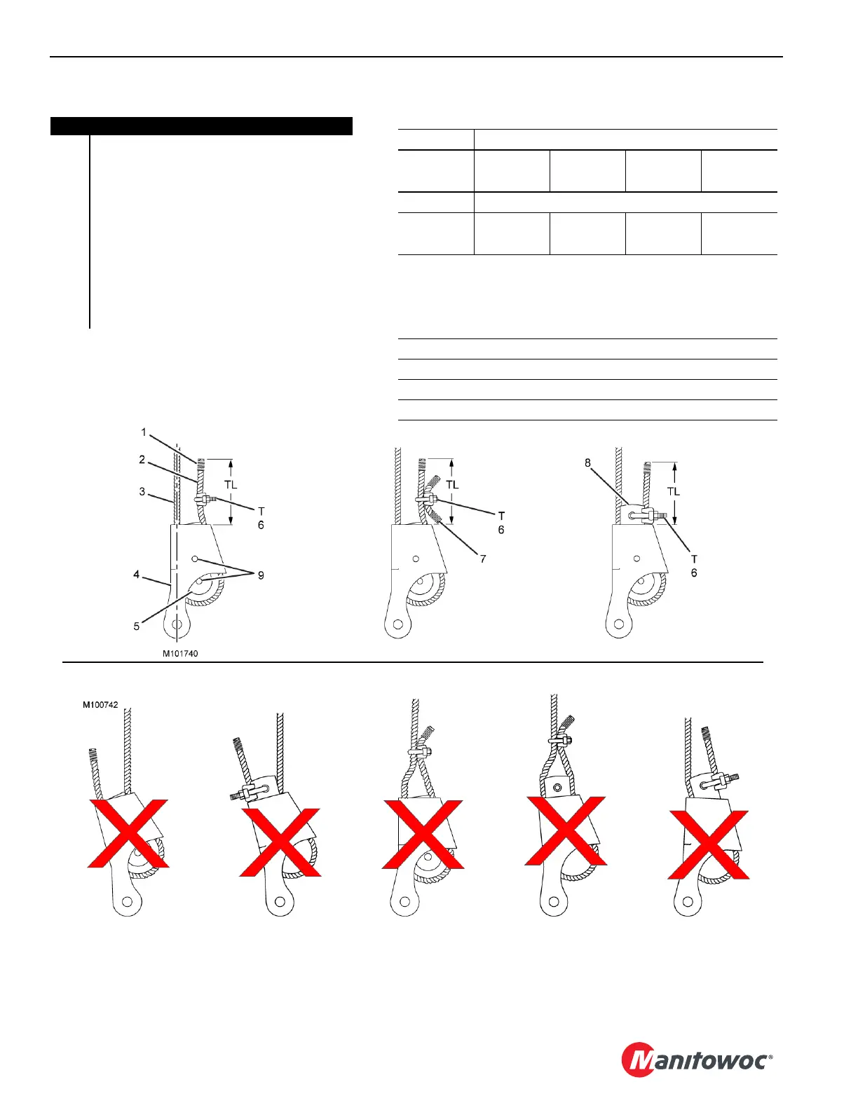
FIGURE 4-160
Item Description
1Seizing
2 Dead End
3 Live End in Straight Line with Socket
4 Socket
5 Wedge
6 Rope Clip
7 Short Piece of Wire Rope
8 Terminator Wedge
9 Shipping Holes: Do not reinstall any shipping
material (bolt, plastic strap, or wire) in shipping
holes of wedge or socket after assembling.
ALL ARE DANGEROUS AND PROHIBITED!
Right!
Method A
WRONG
Rope Backward
WRONG
Rope Backward
WRONG
Dead End Clipped
to Live End
WRONG
Wedge Backward
WRONG
Dead End Clipped
to Live End
T (Rope Clip Nut Torque)
Wire Rope Clip Size
mm
(inch)
22,23
(7/8)
25,4
(1)
28,58
(1-1/8)
31,75
(1-1/4)
Torque
kN/m
*(ft/lb
0,30
(225)
0,30
(225)
0,30
(225)
0,49
(360)
*Tightening torque values shown are based on threads being
clean, dry, and lubrication free.
Right!
Method B
Right!
Method C
TL (Tail Length)
Standard 6 to 8 Strand Wire Rope
Minimum of 6 rope diameters, but not less than 152 mm (6 in).
Rotation Resistant Wire Rope
Minimum of 20 rope diameters, but not less than 152 mm (6 in).