12 Technical data
12.10.1 Time response of the digital inputs
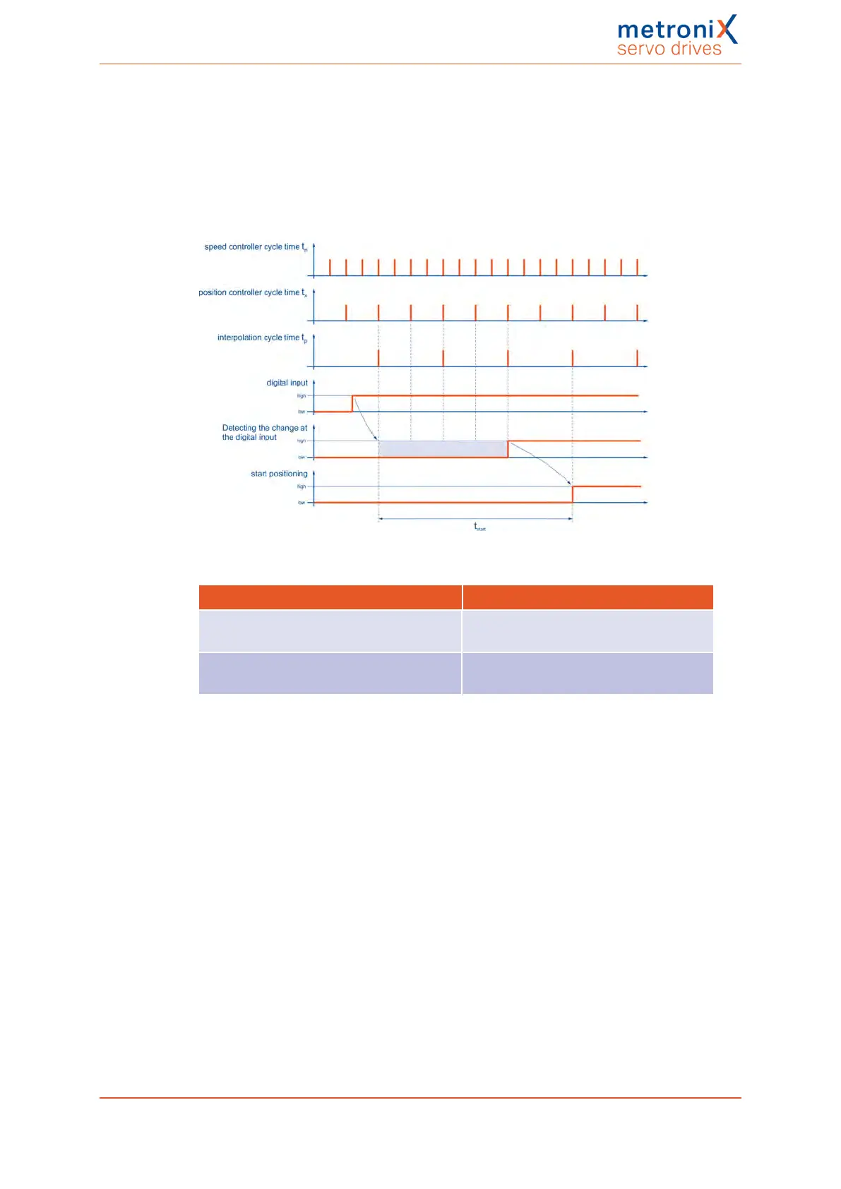
The digital inputs are digitally filtered to improve the interference suppression.
The following illustration shows the filter time mechanism. In addition, the special reaction
to the "Positioning start" function is also shown. Although the signal is evaluated during
the position controller cycle t
x
the start of a movement will be performed within the
interpolation cycle time matrix t
p
.
Figure 127: Filter time mechanism in the case of digital inputs
Parameter Max.
Maximum delay until the start of a position
set becomes active t
start
5 • t
x
+ t
p
Current rise time
(with current feedforward control)
t
n
+ t
i
+ t
pwm
t
x
= position controller cycle time (typically 200 µs with a current controller cycle
time t
i
of 50 µs)
t
n
= speed controller cycle time (typically 100 µs with a current controller cycle time
t
i
of 50 µs)
t
pwm
= half the cycle time of the PWM (corresponds to t
i
)
Product manual BL 4000-C Page 227 of 298
 Loading...

