13 Electrical installation
13.12 Connector: STO [X3]
Dangerous electrical voltage!
Use only PELV circuits for the STO wiring!
Make sure that no jumpers or the like can be inserted parallel to the safety wiring. For
example, use the maximum wire cross-section of 1.5 mm² or suitable wire end sleeves
with insulating collars for the connection to the associated connector.
Configuration on the device [X3]
SC 3.81/08/90F 3.2SN BK BX
Mating connector
BCF 3.81/08/180F SN BK BX
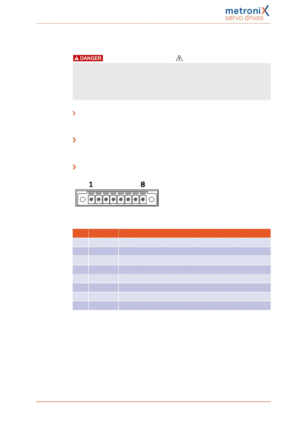
Pin assignment [X3]
Figure 145: STO connector [X3]
Pin Name Description
1 STOA Control input A for the STO function
2 GNDA Reference potential for STO-A
3 STOB Control input B for the STO function
4 GNDB Reference potential for STO-B
5 DIN6 Connected to X1, pin 22
6 DIN7 Connected to X1, pin 10
7 DOUT0 Connected to X1, pin 12
8 GND Reference potential for the auxiliary supply voltage
To ensure the STO ("Safe Torque Off") function, the control inputs STOA and STOB must
be connected in a dual-channel manner with parallel wiring. See section 8.6.1 Safe torque
off (STO) on page 201. This type of connection can be part of an emergency stop circuit or
safety door setup, for example.
Product manual BL 4000-C Page 257 of 298
 Loading...

